The Adafruit Feather Is A Thing

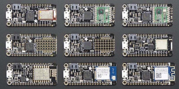
A few years ago, Adafruit launched the Feather 32u4 Basic Proto. This tiny development board featured — as you would expect — an ATMega32u4 microcontroller, a USB port, and a battery charging circuit for tiny LiPo batteries. It was, effectively, a small Arduino clone with a little bit of extra circuitry that made it great for portable and wearable projects. In the years since, and as Adafruit has recently pointed out, the Adafruit Feather has recently become a thing. This is a new standard. Maxim is producing compatible ‘wings’ or shields. If you’re in San Francisco, the streets are littered with Feather-compatible boards. What’s the deal with these boards, and why are there so many of them?

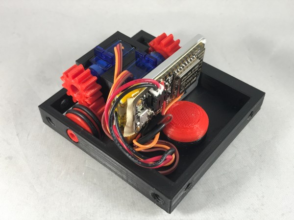
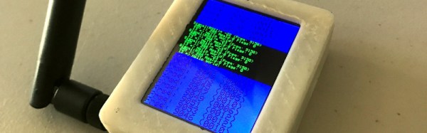
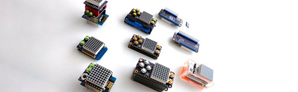
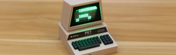
The reason for Adafruit’s introduction of the Feather format was the vast array of shields, hats, capes, clicks, props, booster packs, and various other standards. The idea was to bring various chipsets under one roof, give them a battery charging circuit, and not have a form factor that is as huge as the standard Arduino. The Feather spec was finalized and now we have three-phase energy monitors, a tiny little game console, LoRaWAN Feathers, and CAN controllers.

Of course, the Feather format isn’t just limited to Adafruit products and indie developers. The recently introduced Particle hardware is built on the Feather format, giving cellular connectivity to this better-than-Arduino format. Maxim is producing some development boards with the same format.

So, do we finally have a form factor for one-off embedded development that isn’t as huge or as wonky as the gigantic Arduino with weirdly offset headers? It seems so.

Remember When Scratch-Built Robots Were Hard?

Even simple robots used to require quite a bit of effort to pull together. This example shows how far we’ve come with the tools and techniques that make things move and interact. It’s a 3D printed rover controlled by the touchscreen on your phone. This achieves the most basic building block of wheeled robotics, and the process is easy on you and your pocketbook.

We just can’t stop loving the projects [Greg Zumwalt], aka[gzumwalt], is turning out. We just saw his air-powered airplane engine and now this little rover perks our ears up. The design uses the familiar trick of two powered wheels with a ball bearing to avoid problems with differential turning. But the simplicity is all in the implementation.

This bot is 3D printed using eight very simple pieces: four gears, two axles, a cap and a single tray to mount everything. The cap captures the ball bearing which pokes out a hole in the bottom of the tray to form an omnidirectional wheel. Two 9G servos modified for continuous rotation. The mating teeth of the gears are found on the wheel sections which have grooves for neoprene O-rings to provide traction. The entire thing is driven by an ESP8266 in the form of an Adafruit Feather Huzzah. This is programmed using the Arduino IDE and your phone can connect directly or through a WiFi router.

We’re not crazy, right? Robots didn’t used to be this easy to pull together? This goes for the power of 3D printing versus traditional basement fabrication methods, but in the availability of powerful yet inexpensive embedded systems and the available tools and libraries to program them. Kudos to you [Greg] for showing us how great the currently available building blocks are in the hands of anyone who wants to channel their engineering creativity. He certainly has… this chassis ultimately powers Santa’s sleigh.

Need a bigger printing challenge? Here’s a 3D printed rover that goes all-in with the suspension system.

Continue reading “Remember When Scratch-Built Robots Were Hard?”

Sniff Your Local LoRa Packets

As the LoRa low-bandwidth networking technology in license-free spectrum has gained traction on the wave of IoT frenzy, LoRa networks have started to appear in all sorts of unexpected places. Sometimes they are open networks such as The Things Network, other times they are commercially available networks, and then, of course, there are entirely private LoRa installations.

If you are interested in using LoRa on a particular site, it’s an interesting exercise to find out what LoRa traffic already exists, and to that end [Joe Broxson] has put together a useful little device. Hardware wise it’s an Adafruit Cortex M0 Feather with onboard LoRa module, paired with a TFT FeatherWing for display, and software wise it scans a set of available frequencies and posts any packets it finds to the scrolling display. It also has the neat feature of logging packets in detail to an SD card for later analysis. The whole is enclosed in a 3D printed case from an Adafruit design and makes for a very attractive self-contained unit.

We’ve featured quite a few LoRa projects here, including this one with a Raspberry Pi Compute module in a remote display. Of more relevance in a LoRa testing sense though is this look at LoRa range testing.

Hackaday Prize Best Product Finalist: PewPew

This year for the Hackaday Prize, we’re doing something very, very cool. We’re encouraging hardware entrepreneurs to come up with the next big electronic thing. We’re giving the Best Product in the Hackaday Prize $30,000, and an opportunity to work in a lab filled with tools to turn that prototype into a marketable reality.

Last week, we announced the twenty finalists of the Hackaday Prize Best Product competition. There’s still a lot of work these hackers and tinkerers need to do before the final judging round, but until then we can start taking a look at what are already some of the finest products in this year’s Hackaday Prize.

For his entry into the Best Product finals, [Radomir] is working on a game machine. Consider this an educational toy. Game programming is hard, and some talent is required to go from the main loop to handling buttons to pushing pixels. This project is the minimal game machine. It’s a FeatherWing for Adafruit’s family of micro dev boards meant to teach PyGame programming.

On this board is an 8×8 matrix of bi-color LEDs, a few switches, resistors, and a chip that turns those LEDs into something that can be memory mapped. It’s simple, but that’s the point: it’s a minimum viable product to teach game programming.

Right now, the business plan is to develop games and examples for this add-on board, build a community, write a few tutorials, and sell a few of these boards on Tindie. From there, it’s just a matter of growing, and there are already plans for a PewPew wing with a TFT screen, an STM32 processor, and a tile and sprite engine built in. This could very well be the beginnings of a very cool educational toy, and we’re happy to have it as a finalist in the Best Product competition of the Hackaday Prize.

Mini Retro PET Computer

There was a time that the Commodore PET was the standard computer at North American schools. It’s all-in-one, rugged construction made it ideal for the education market and for some of us, the PET started a life-long love affair with computers. [Ruiz Brothers] at Adafruit has come up with a miniature PET model run on a microcontroller and loaded up with a green LED matrix for a true vintage look.

While not a working model of a PET, the model runs on an Adafruit Feather M0 Basic Proto which is an Atmel ATSAMD21 Cortex M0 microcontroller and can display graphics on Adafruit’s 16×9 charlieplexed led matrix.The ATSAMD21 is the chip used in the Arduino Zero, so I’m sure we’ll see more of this chip in the future. Like all of the tutorials at Adafruit, this one is very detailed with step-by-step animated pictures to help you along. Obviously, you don’t need the exact hardware that they’re using, but if you’re putting in an order from Adafruit anyway, why not?

The plans for the 3D printed PET are available for free, so even if you don’t want to put their LED matrix and microcontroller in it, you can still print yourself out a great looking prop and 3D printing the PET will only use about a dollar’s worth of filament. Of course, while this is a cool retro model, if you have a Commodore PET lying around, you could probably do something else with it. We don’t, so that sound you hear is the sound of our 3D printer printing up the past.

Continue reading “Mini Retro PET Computer”

Rotary Cell Phone: Blast From A Past That Never Was

The 1970s called and they want their rotary dial cell phone back.

Looking for all the world like something assembled from the Radio Shack parts department – remember when Radio Shack sold parts? – [Mr_Volt]’s build is a celebration of the look and feel of a hobbyist build from way back when. Looking a little like a homebrew DynaTAC 8000X, the brushed aluminum and 3D-printed ABS case sports an unusual front panel feature – a working rotary dial. Smaller than even the Trimline phone’s rotating finger stop dial and best operated with a stylus, the dial translates rotary action to DTMF tones for the Feather FONA board inside. Far from a one-trick pony, the phone sports memory dialing, SMS messaging, and even an FM receiver. But most impressive and mysterious is the dial mechanism, visible through a window in the wood-grain back. Did [Mr_Volt] fabricate those gears and the governor? We’d love to hear the backstory on that.

This isn’t the first rotary cell phone hybrid we’ve featured, of course. There was this GSM addition to an old rotary phone and this cell phone that lets you slam the receiver down. But for our money a rotary dial cell phone built from the ground up wins the retro cool prize of the bunch.

Continue reading “Rotary Cell Phone: Blast From A Past That Never Was”

Hackaday Prize Entry: $50 Foot Controlled Mouse

ALS robbed one of [C. Niggel]’s relative’s of the use of their upper body. This effectively imprisoned them in their house; ALS is bad stuff. Unfortunately too, the loss of upper body mobility meant that they couldn’t even use the computer to interact with people and the outside world. However, one day [C. Niggel] noted that the relative’s new electric wheelchair was foot controlled. Could this be adapted to a computer mouse?

He looked up commercial solutions and found them not only prohibitively expensive, but also fraught with proprietary drivers and all sorts of bad design nonsense. With all of the tools out there today there was no reason this couldn’t be quickly prototyped and sent to the relative in need.

He used a combination of conductive thread, neoprene, and velostat to build the pads themselves. The pads were balanced with some adjusting resistors in series. The signals are sent to an Adafruit Feather board which interprets them and converts it to a PS/2 standard.

The first version of the mouse used separate pads glued to a MDF board with contact cement. However this, along with some other initial design flaws, resulted in premature failure of the mouse. [C. Niggel] quickly returned to the lab and produced a new version with more robust construction and mailed it off. So far so good!