All other things being equal, signals with wider bandwidth can carry more information. Sometimes that information is data, but sometimes it is frequency. AM radio stations (traditionally) used about 30 kHz of bandwidth, while FM stations consume nearly 200 kHz. Analog video signals used to take up even more space. However, your brain is a great signal processor. To understand speech, you don’t need very high fidelity reproduction.
Radio operators have made use of that fact for years. Traditional shortwave broadcasts eat up about 10kHz of bandwidth, but by stripping off the carrier and one sideband, you can squeeze the voice into about 3 kHz and it still is intelligible. Typical voice codecs (that is, something that converts speech to digital data and back) use anywhere from about 6 kbps to 64 kbps.
[David Rowe] wants to change that. He’s working on a codec for ham radio use that can compress voice to 700 bits per second. He is trying to keep the sound quality similar to his existing 1,300 bit per second codec and you can hear sound samples from both in his post. You’ll notice the voices sound almost like old-fashioned speech synthesis, but it is intelligible.
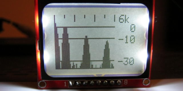
The “normal” way to build a spectrum analyzer is to collect a bunch of samples and run a Fast Fourier Transform (FFT) on them all in one shot. As the name implies, the FFT is fast, and the result is the frequency components of the sampled data. [agp.cooper]’s “wrong” way to do it takes the Goertzel algorithm, which is used for detecting the intensity of a particular frequency, and scanning across the frequency range of interest. It’s a lot slower than a single FFT but, importantly for the ATtiny85 that he implements this on, it’s less demanding of the RAM.
Swear on broadcast television and they’re going to bleep out the audio to protect the sensibilities of the general public. Swear bleeps are fairly standardised at 1kHz, or so [mechatronicsguy] tells us. You learn something new every day.
OK, it’s not as though there’s an ISO document somewhere detailing the exact tone to use when someone says a naughty word on camera, it is far more likely that a 1kHz tone is the most likely frequency to be at hand in a studio. It’s so ubiquitous that even audio engineers with nowhere near perfect pitch can identify it, and one to which an acquaintance of ours swears years of exposure have given his ears a selective notch filter.
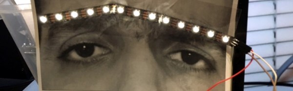
Armed with this information, [mechatronicsguy] created a fun project. As a fan of the [electroBOOM] Youtube channel he made a set of LED eyebrows for a picture of his bleep-prone hero, and using a Teensy with its audio and FFT libraries he made them light up whenever a 1kHz tone is detected. It’s not the most amazing of hacks, but if you find yourself in need of a smile on a chilly November morning then maybe it’ll have the same effect on you as it did with us. He’s posted a quick video of the ‘brows in action which we’ve embedded below the break.
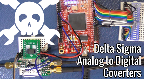
In part one, I compared the different Analog to Digital Converters (ADC) and the roles and properties of Delta Sigma ADC’s. I covered a lot of the theory behind these devices, so in this installment, I set out to find a design or two that would help me demonstrate the important points like oversampling, noise shaping and the relationship between the signal-to-noise ratio and resolution.
Modulator Implementation
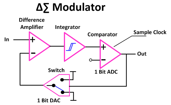
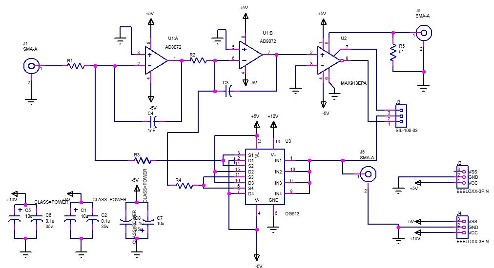
Check out part one to see the block diagrams of what what got us to here. The schematics shown below are of a couple of implementations that I played with depicting a single-order and a dual-order Delta Sigma modulators.
Basically I used a clock enabled, high speed comparator, with two polarities in case I got it the logic backwards in my current state of burn out to grey matter ratio. The video includes the actual schematic used.
Since I wasn’t designing for production I accepted the need for three voltages since my bench supply was capable of providing them and this widget is destined for the drawer with the other widgets made for just a few minutes of video time anyway. Continue reading “Tearing Into Delta Sigma ADCs Part 2”→
It’s not surprising that Analog to Digital Converters (ADC’s) now employ several techniques to accomplish higher speeds and resolutions than their simpler counterparts. Enter the Delta-Sigma (Δ∑) ADC which combines a couple of techniques including oversampling, noise shaping and digital filtering. That’s not to say that you need several chips to accomplish this, these days single chip Delta-Sigma ADCs and very small and available for a few dollars. Sometimes they are called Sigma-Delta (∑Δ) just to confuse things, a measure I applaud as there aren’t enough sources of confusion in the engineering world already.
I’m making this a two-parter. I will be talking about some theory and show the builds that demonstrate Delta-Sigma properties and when you might want to use them.
Every machine has its own way of communicating with its operator. Some send status emails, some illuminate, but most of them vibrate and make noise. If it hums happily, that’s usually a good sign, but if it complains loudly, maintenance is overdue. [Ariel Quezada] wants to make sense of machine vibrations and draw conclusions about their overall mechanical condition from them. With his project, a 3-axis Open Source FFT Spectrum Analyzer he is not only entering the Hackaday Prize 2016 but also the highly contested field of acoustic defect recognition.
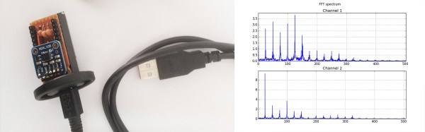
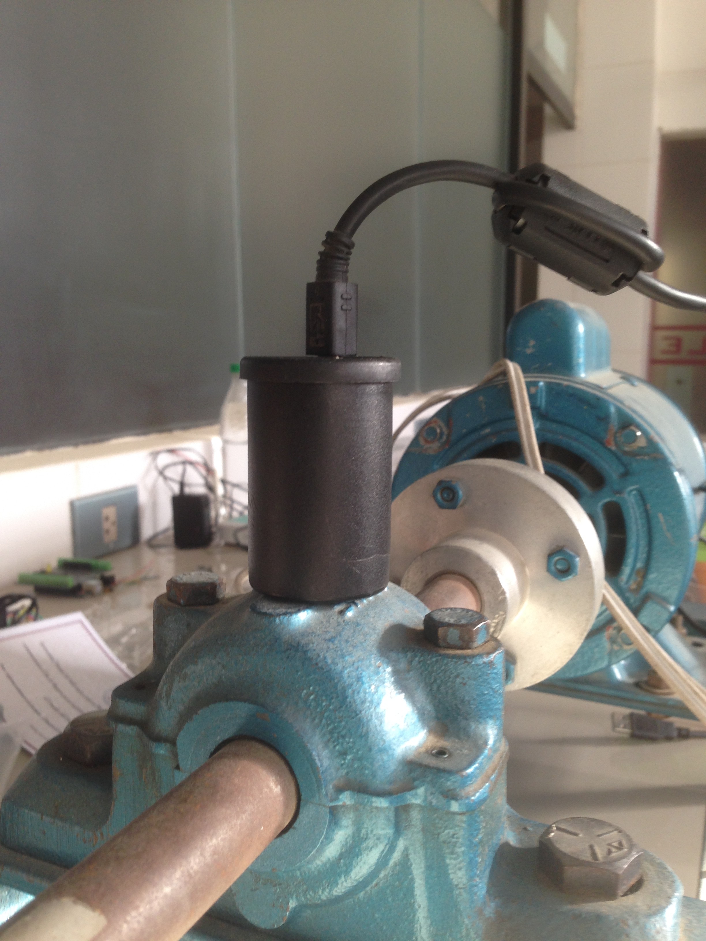
For the hardware side of the spectrum analyzer, [Ariel] equipped an Arduino Nano with an ADXL335 accelerometer, which is able to pick up vibrations within a frequency range of 0 to 1600 Hz on the X and Y axis. A film container, equipped with a strong magnet for easy installation, serves as an enclosure for the sensor. The firmware [Ariel] wrote is an efficient piece of code that samples the analog signals from the accelerometer in a free running loop at about 5000 Hz. It streams the digitized waveforms to a host computer over the serial port, where they are captured and stored by a Python script for further processing.
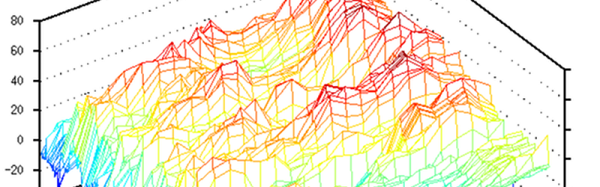
From there, another Python script filters the captured waveform, applies a window function, calculates the Fourier transform and plots the spectrum into a graph. With the analyzer up and running, [Ariel] went on testing the device on a large bearing of an arbitrary rotating machine he had access to. A series of tests that involved adding eccentric weights to the rotating shaft shows that the analyzer already makes it possible to discriminate between different grades of imbalance.
A few years ago, [Artem] learned about ways to focus sound in an issue of Popular Mechanics. If sound can be focused, he reasoned, it could be focused onto a plane of microphones. Get enough microphones, and you have a ‘sound camera’, with each microphone a single pixel.
Movies and TV shows about comic books are now the height of culture, so a device using an array of microphones to produce an image isn’t an interesting demonstration of FFT, signal processing, and high-speed electronic design. It’s a Daredevil camera, and it’s one of the greatest builds we’ve ever seen.
[Artem]’s build log isn’t a step-by-step process on how to make a sound camera. Instead, he went through the entire process of building this array of microphones, and like all amazing builds the first step never works. The first prototype was based on a flatbed scanner camera, simply a flatbed scanner in a lightproof box with a pinhole. The idea was, by scanning a microphone back and forth, using the pinhole as a ‘lens’, [Artem] could detect where a sound was coming from. He pulled out his scanner, a signal generator, and ran the experiment. It didn’t work. The box was not soundproof, the inner chamber should have been anechoic, and even if it worked, this camera would only be able to produce an image or two a minute.
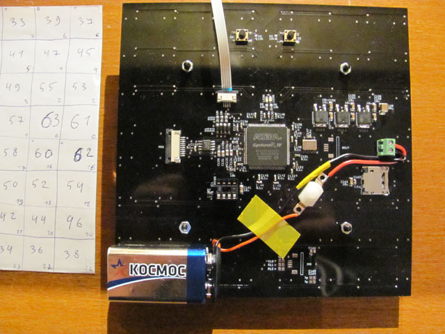
8×8 microphone array (mics on opposite side) connected to Altera FPGA at the center
The idea sat in the shelf of [Artem]’s mind for a while, and along the way he learned about FFT and how the gigantic Duga over the horizon radar actually worked. Math was the answer, and by using FFT to transform a microphones signals from up-and-down to buckets of frequency and intensity, he could build this camera.
That was the theory, anyway. Practicality has a way of getting in the way, and to build this gigantic sound camera he would need dozens of microphones, dozens of amplifiers, and a controller with enough analog pins, DACs, and processing power to make sense of all of this.
This complexity collapsed when [Artem] realized there was an off-the-shelf part that was a perfect microphone camera pixel. MEMS microphones, like the kind found in smartphones, take analog sound and turn it into a digital signal. Feed this into a fast enough microcontroller, and you can perform FFT on the signal and repeat the same process on the next pixel. This was the answer, and the only thing left to do was to build a board with an array of microphones.
[Artem]’s camera microphone is constructed out of several modules, each of them consisting of an 8×8 array of MEMS microphones, controlled via FPGA. These individual modules can be chained together, and the ‘big build’ is a 32×32 array. After a few problems with manufacturing, the board actually worked. He was recording 64 channels of audio from a single panel. Turning on the FFT visualization and pointing it at a speaker revealed that yes, he had indeed made a sound camera.
The result is a terribly crude movie with blobs of color, but that’s the reality of a camera that only has 32×32 resolution. Right now the sound camera works, the images are crude, and [Artem] has a few ideas of where to go next. A cheap PC is fast enough to record and process all the data, but now it’s an issue of bandwidth; 30 sounds per second is a total of 64 Mbps of data. That’s doable, but it would need another FPGA implementation.
Is this sonic vision? Yes, technically the board works. No, in that the project is stalled, and it’s expensive by any electronic hobbyist standards. Still, it’s one of the best to grace our front page.


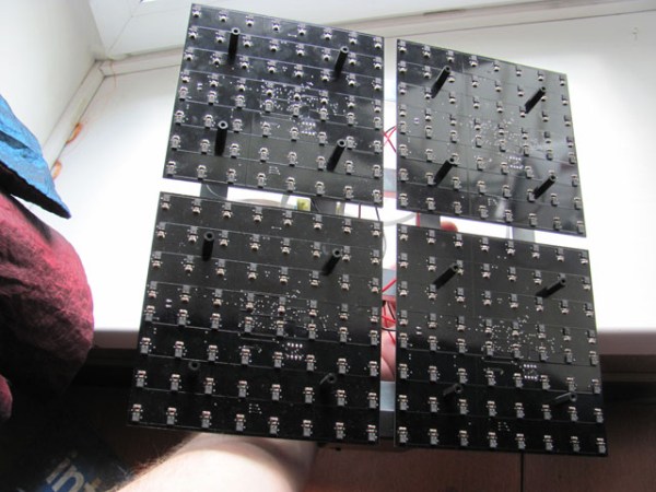
 [Artem]’s camera microphone is constructed out of several modules, each of them consisting of an 8×8 array of MEMS microphones, controlled via FPGA. These individual modules can be chained together, and the ‘big build’ is a 32×32 array. After a few problems with manufacturing, the board actually worked. He was recording 64 channels of audio from a single panel. Turning on the FFT visualization and pointing it at a speaker revealed that yes, he had indeed made a sound camera.


