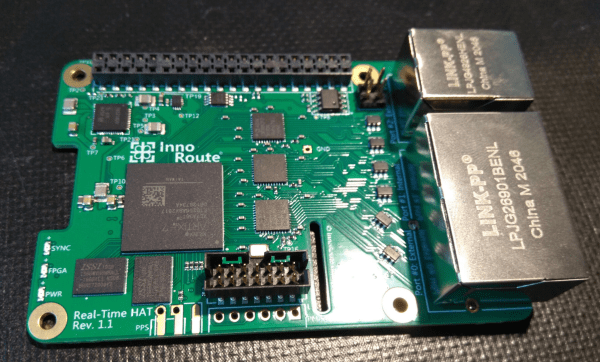
Accurate Digital Clock Keeps Ticking With FPGA

Even the most punctual among us are content to synchronize their clocks to external time sources like navigation satellite constellations, network time servers, frequency-controlled AC mains, or signals broadcast by radio stations such as WWV, CHU, and DFC77 — but not [zaphod]. After building a couple of more traditional clocks over the years, he set his sights on making a completely isolated digital clock that doesn’t rely on external synchronization (well, except to initialize the time at first power-up).

The accuracy goal he set for himself was that of a Casio F-91W wristwatch, which is specified to maintain +/- 30 seconds per month (about 12 ppm). At the heart of the design is an oven-controlled crystal oscillator whose stability is in the single-digits parts-per-billion.

The counter chain that accumulates the time is implemented in an FPGA — admittedly overkill, but [zaphod] wanted to learn FPGA programming for this project as well. An ATmega328 drives the display and does other bookkeeping tasks. The whole design is partitioned into three PCBs which fit inside a custom 3D-printed case.

[zaphod] does a thorough job documenting his build, including the bugs and failures along the way. We like the honest summary he wrote at the project’s conclusion, noting things that could be improved or should have been done differently. Be sure to check out the GitHub repository, where all the source code and PCB design files are posted. How accurate is your wristwatch, if you even wear one anymore?

Custom RISC-V Processor Built In VHDL

While ARM continues to make inroads into the personal computing market against traditional chip makers like Intel and AMD, it’s not a perfect architecture and does have some disadvantages. While it’s a great step on the road to software and hardware freedom, it’s not completely free as it requires a license to build. There is one completely open-source and free architecture though, known as RISC-V, and its design and philosophy allow anyone to build and experiment with it, like this build which implements a RISC-V processor in VHDL.

Since the processor is built in VHDL, a language which allows the design and simulation of integrated circuits, it is possible to download the code for the processor and then program it into virtually any FPGA. The processor itself, called NEORV32, is designed as a system-on-chip complete with GPIO capabilities and of course the full RISC-V processor implementation. The project’s creator, [Stephan], also struggled when first learning about RISC-V so he went to great lengths to make sure that this project is fully documented, easy to set up, and that it would work out-of-the-box.

Of course, since it’s completely open-source and requires no pesky licensing agreements like an ARM platform might, it is capable of being easily modified or augmented in any way that one might need. All of the code and documentation is available on the project’s GitHub page. This is the real benefit of fully open-source hardware (or software) which we can all get behind, even if there are still limited options available for RISC-V personal computers for the time being.

How does this compare to VexRISC or PicoSOC? We don’t know yet, but we’re always psyched to have choices.

Slice Your Next FPGA Design

A recent trend has been to convert high-level constructs into FPGA code like Verilog or VHDL. Silice goes the other way: it converts very hardware-specific concepts to Verilog and aims to be a more expressive and easier to use language.

Why Silice? The project’s web page enumerates its design goals:

  • A clean, simple syntax that clearly exposes the flow of operations and where clock cycles are spent.
  • Precise rules regarding flow control (loops, calls) and their clock cycle consumption.
  • Familiar hardware constructs such as always blocks, instantiation, expression tracking (wires).
  • An optional flow-control oriented design style (automatic FSM generation), that naturally integrates within a design: while, break, subroutines.
  • The possibility to easily describe pipelines.
  • Automatically takes care of creating flip-flops for variables, with automatic pruning (e.g. const or bindings).
  • Generic interfaces and grouped IOs for easy reuse and modular designs.
  • Generic circuits that can be instantiated and reused easily.
  • Explicit clock domains and reset signals.
  • Familiar syntax with both C and Verilog inspired elements.
  • Inter-operates with Verilog, allowing to import and reuse existing modules.
  • Powerful LUA-based pre-processor.

Continue reading “Slice Your Next FPGA Design”

Arduboy On The Big Screen

We’re big fans of the Arduboy here at Hackaday, but we’ll admit its tiny screen isn’t exactly ideal for long gaming sessions. There are some DIY builds of the open source handheld that use a larger SPI OLED display, though you’re relatively limited on what kind of changes can be made to the hardware before the games start balking. But as [Nick Bild] shows with his Arduboy home console, hacking the core system library opens up a lot of interesting possibilities.

Games written for the Arduboy make use of a common library that handles all the low-level hardware stuff, which includes a display() function to push the graphical data out to an SPI-connected OLED display. What [Nick] has done is re-write that function to instead output to a custom VGA generator running on the TinyFPGA BX. He had to delete support for the Arduboy’s RGB LEDs because he needed the extra pins, but that shouldn’t cause much of a problem in terms of software support.

This does mean that games need to be recompiled against the modified library to work on his hardware, but as the vast majority of Arduboy software is open source anyway, that’s not much of a problem. We particularly like the Super Game Boy style border  you get around the display at no extra cost.

At this point the hardware looks less like a console and more like a breadboard filled with jumpers, so we’re interested in seeing this project taken to its logical conclusion. A custom PCB, enclosure, and possibly even support for using the original NES controllers would turn this into proper system worthy of any hacker’s game room. You could even put the games on custom cartridges if you wanted, though a flash chip that holds the system’s entire library would be quite a bit more convenient.

FIR Filters For Xilinx

Digital filters are always an interesting topic, and they are especially attractive with FPGAs. [Pabolo] has been working with them in a series of blog posts. The latest covers an 8th order FIR filter in Verilog.  He covers some math, which you can find in many places, but he also shows how an implementation maps to DSP slices in a device. Then to reduce the number of slices, he illustrates folding which trades delay time for slice usage.

Folding takes a multi-stage parallel multiplication and breaks it into fewer multiplications done over a longer period of time. This reuses slices to reduce the number required for high-order filters.

Continue reading “FIR Filters For Xilinx”

Arduino And FPGA Done Differently

FPGA guru [Max Maxfield] recently took a look at the XLR8 (pronounced accelerate) board from a company called Alorium. On the surface, it looks like another Arduino UNO clone. But instead of a CPU, it contains an Intel MAX10 FPGA that runs a softcore AVR processor. Of course, that’s only part of the story. If the board was just a mock Arduino using an FPGA, that’s not very interesting for practical purposes. However, by incorporating accelerator blocks or XBs, you can add FPGA modules to the soft CPU. [Max] shows an example that you can see in the video below where an FPGA block controls servos more easily than a standard Arduino. There’s also a version that looks like an Arduino Nano, but can clock much faster as well as use the XBs.

In addition to prebuilt XBs, there is a workflow to build your own if you are familiar with working with FPGAs. The products aren’t exactly new, but we enjoyed [Max’s] take on the product. We also appreciated the simple code examples showing exactly how you would convert a program to use the accelerated functions. Continue reading “Arduino And FPGA Done Differently”

Surf’s Up, A Styrofoam Ball Rides The Waves To Create A Volumetric Display

We are big fans of POV displays, particularly ones that move into 3D. To do so, they need to move even faster than their 2D cousins. [danfoisy] built a volumetric display that doesn’t move LEDs or any other digital display through space, or project light onto a moving surface. All that moves here is a bead of styrofoam and does so at up to 1 meter per second. Having low mass certainly helps when trying to hit the brakes, but we’re getting ahead of ourselves.

danfoisy vdatp 3d simulation

[danfoisy] and son built an acoustic levitator kit from [PhysicsGirl] which inspired the youngster’s science fair project on sound. See the video by [PhysicsGirl] for an explanation of levitation in a standing wave. [danfoisy] happened upon a paper in the Journal Nature about a volumetric display that expanded this one-dimensional standing wave into three dimensions. The paper described using a phased array of ultrasonic transducers, each with a 40 kHz waveform.

After reading the paper and determining how to recreate the experiment, [danfoisy] built a 2D simulation and then another in 3D to validate the approach. We are impressed with the level of physics and programming on display, and that the same code carried through to the build.

[danfoisy] didn’t stop with the simulations, designing and building control boards for each 100 x 100 10 x 10 grid of transducers. Each grid is driven by 2 Intel Cyclone FPGAs and all are fed 3D shapes by a Raspberry Pi Zero W. The volume of the display is 100 mm x 100 mm x 145mm and the positioning of the foam ball is accurate down to .01 mm though currently there is considerable distortion in the positioning.

Check out the video after the break to see the process of simulating, designing, and testing the display. There are a number of tips along the way, including how to test for the polarity of the transducers and the use of a Python script to place the grids of transducers and drivers in KiCad.

danfoisy vdatp schematic  danfoisy vdatp board layout

Continue reading “Surf’s Up, A Styrofoam Ball Rides The Waves To Create A Volumetric Display”