Spy Transceiver Makes Two Tubes Do The Work Of Five

Here at Hackaday, we love following along with projects as they progress. That’s especially true when a project makes a considerable leap in terms of functionality from one version to another, or when the original design gets more elegant. And when you get both improved function and decreased complexity at the same time? That’s the good stuff.

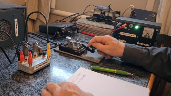
Take the recent improvements to a vacuum tube “spy radio” as an example. Previously, [Helge (LA6NCA)] built both a two-tube transmitter and a three-tube receiver, either of which would fit in the palm of your hand. A little higher math seems to indicate that combining these two circuits into a transceiver would require five tubes, but that’s not how hams like [Helge] roll. His 80-m CW-only transceiver design uses only two tubes and a lot of tricks, which we admit we’re still wrapping our heads around. On the receive side, one tube serves as a mixer/oscillator, combining the received signal with a slightly offset crystal-controlled signal to provide the needed beat frequency. The second tube serves as the amplifier, both for the RF signal when transmitting, and for audio when receiving.

The really clever part of this build is that [Helge] somehow stuffed four separate relays into the tiny Altoids tin chassis. Three of them are used to switch between receive and transmit, while the fourth is set up as a simple electromagnetic buzzer. This provides the sidetone needed to effectively transmit Morse code, and is about the simplest way we’ve ever seen to address that need. Also impressive is how [Helge] went from a relatively expansive breadboard prototype to a much more compact final design, and how the solder was barely cooled before he managed to make a contact over 200 km. The video below has all the details.

Continue reading “Spy Transceiver Makes Two Tubes Do The Work Of Five”

Low-Cost RF Power Sensor Gets All The Details Right

Dirty little secret time: although amateur radio operators talk a good game about relishing the technical challenge of building their own radio equipment, what’s really behind all the DIY gear is the fact that the really good stuff is just too expensive to buy.

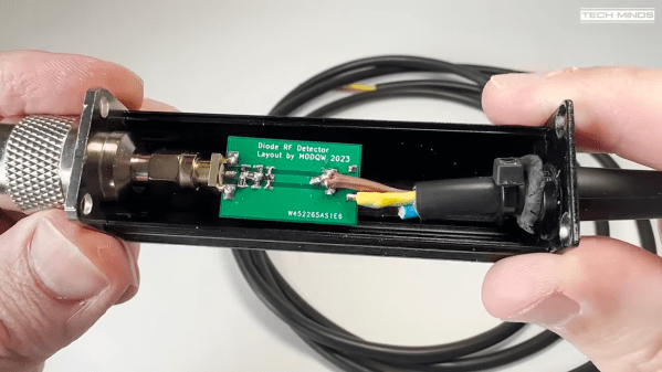
A case in point is this super-low-cost RF power sensor that [Tech Minds (M0DQW)] recently built. It’s based on a design by [DL5NEG] that uses a single Schottky diode and a handful of passive components. The design is simple, but as with all things RF, details count. Chief among these details is the physical layout of the PCB, which features a stripline of precise dimensions to keep the input impedance at the expected 50 ohms. Also important are the number and locations of the vias that stitch the ground planes together on the double-sided PCB.

While [Tech Minds]’ first pass at the sensor hewed closely to the original design and used a homebrew PCB, the sensor seemed like a great candidate for translating to a commercial PCB. This version proved to be just as effective as the original, with the voltage output lining up nicely with the original calibration curves generated by [DL5NEG]. The addition of a nice extruded aluminum case and an N-type RF input made for a very professional-looking tool, not to mention a useful one.

[Tech Minds] is lucky enough to live within view of QO-100, ham radio’s first geosynchronous satellite, so this sensor will be teamed up with an ADC and a Raspberry Pi to create a wattmeter with a graphical display for his 2.4-GHz satellite operations.

Continue reading “Low-Cost RF Power Sensor Gets All The Details Right”

Tiny Three-Tube Receiver Completes Spy Radio Suite

In our surface-mount age, it’s easy to be jaded about miniaturization. We pretty much expect every circuit to be dimensionally optimized, something that’s easy to do when SMDs that rival grains of sand are available. But dial the calendar back half a century or so and miniaturization was a much more challenging proposition.

Challenging, perhaps, but by no means unachievable, as [Helge Fyske (LA6NCA)] demonstrates with this ultra-compact regenerative vacuum tube receiver. It’s a companion to his recent “spy transmitter,” a two-tube radio built in — or on, really — an Altoids tin. The transmitter was actually a pretty simple circuit, just a crystal-controlled oscillator and an RF amplifier really, but still managed about 1.5 Watts output on the 80-meter ham band.

The receiver circuit ended up being much more complicated, as receivers do, and therefore harder to cram into the allotted space. [Helge]’s used a three-tube regenerative design, with one tube each devoted to the RF amp, detector/mixer, and audio amplifier stages. As in the transmitter, the receiver tubes are mounted on the outside of the box, with the inside crammed full of components. [Helge] had to be quite careful about component positioning, to prevent interstage coupling and other undesirable side effects of building in such close quarters.

Was it worth it? Judging by the video below, absolutely! We’ve rarely heard performance like that from even a modern receiver with all the bells and whistles, let alone from a homebrew design under such constraints. It sounds fantastic, and hats off to [Helge] for completing his spy radio suite in style.

Continue reading “Tiny Three-Tube Receiver Completes Spy Radio Suite”

Your Multimeter Might Be Lying To You

Multimeters are indispensable tools when working on electronics. It’s almost impossible to build any but the most basic of circuits without one to test and troubleshoot potential issues, and they make possible a large array of measurement capabilities that are not easily performed otherwise. But when things start getting a little more complex it’s important to know their limitations, specifically around what they will tell you about circuits designed for high frequency. [watersstanton] explains in this video while troubleshooting an antenna circuit for ham radio.

The issue that often confuses people new to radio or other high-frequency projects revolves around the continuity testing function found on most multimeters. While useful for testing wiring and making sure connections are solid, they typically only test using DC. When applying AC to the same circuits, inductors start to offer higher impedance and capacitors lower impedance, up to the point that they become open and short circuits respectively. The same happens to transformers, but can also most antennas which often look like short circuits to ground at DC but can offer just enough impedance at their designed frequency to efficiently resonate and send out radio waves.

This can give some confusing readings, such as when testing to make sure that a RF connector isn’t shorted out after soldering it to a coaxial cable for example. If an antenna is connected to the other side, it’s possible a meter will show a short at DC which might indicate a flaw in the soldering of the connector if the user isn’t mindful of this high-frequency impedance. We actually featured a unique antenna design recently that’s built entirely on a PCB that would show this DC short but behaves surprisingly well when sending out WiFi signals.

Continue reading “Your Multimeter Might Be Lying To You”

Arbitrary Code Execution Over Radio

Computers connected to networks are constantly threatened by attackers who seek to exploit vulnerabilities wherever they can find them. This risk is particularly high for machines connected to the Internet, but any network connection can be susceptible to attacks. As highlighted by security researcher and consultant [Rick Osgood], even computers connected to nothing more than a radio can be vulnerable to attacks if they’re using certain digital modes of communication.

The vulnerability that [Rick] found involves exploiting a flaw in a piece of software called WinAPRS. APRS is a method commonly used in the amateur radio community for sending data over radio, and WinAPRS allows for this functionality on a PC. He specifically sought out this program for vulnerabilities since it is closed-source and hasn’t been updated since 2013. After some analysis, he found a memory bug which was used to manipulate the Extended Instruction Pointer (EIP) register which stores the memory address of the next instruction to be executed by the CPU. This essentially allows for arbitrary code execution on a remote machine via radio.

The exploit was found while using Windows XP because it lacks some of the more modern memory protection features of modern operating systems, but the exploit does still work with Windows 10, just not as reliably and with a bit of extra effort required. It’s a good reminder to use open-source software when possible so issues like these can get resolved, and to regularly install security updates when possible. If you’re looking to delve into the world of APRS in more modern times, take a look at this project which adds APRS to budget transceivers. Just make sure you get your license first.

Hackaday Links Column Banner

Hackaday Links: April 2, 2023

It may be hard to believe, but it’s time for the Hackaday Prize again! The 2023 Hackaday Prize was announced last weekend at Hackaday Berlin, and entries are already pouring in. The first-round challenge is all about “Re-engineering Education,” which means you’ve got to come up with a project idea that helps push back the veil of ignorance somehow. Perhaps you’ve got a novel teaching tool in mind, or a way to help students learn remotely. Or maybe your project is aimed at getting students involved and engaged. Whatever it is — and whatever the subject matter; it doesn’t just have to be hacking-adjacent — get an entry together, build a team, and get to work. The first round closes on April 25, so get to it!

Continue reading “Hackaday Links: April 2, 2023”

Two-Tube Spy Transmitter Fits In The Palm Of Your Hand

It’s been a long time since vacuum tubes were cutting-edge technology, but that doesn’t mean they don’t show up around here once in a while. And when they do, we like to feature them, because there’s still something charming, nay, romantic about a circuit built around hot glass and metal. To wit, we present this compact two-tube “spy radio” transmitter.

From the look around his shack — which we love, by the way — [Helge Fykse (LA6NCA)] really has a thing for old technology. The typewriter, the rotary phones, the boat-anchor receiver — they all contribute to the retro feel of the space, as well as the circuit he’s working on. The transmitter’s design is about as simple as can be: one tube serves as a crystal-controlled oscillator, while the other tube acts as a power amplifier to boost the output. The tiny transmitter is built into a small metal box, which is stuffed with the resistors, capacitors, and homebrew inductors needed to complete the circuit. Almost every component used has a vintage look; we especially love those color-coded mica caps. Aside from PCB backplane, the only real nod to modernity in the build is the use of 3D printed forms for the coils.

But does it work? Of course it does! The video below shows [Helge] making a contact on the 80-meter band over a distance of 200 or so kilometers with just over a watt of power. The whole project is an excellent demonstration of just how simple radio communications can be, as well as how continuous wave (CW) modulation really optimizes QRP setups like this.

Continue reading “Two-Tube Spy Transmitter Fits In The Palm Of Your Hand”