Evolving The 3D Printed Linear Actuator

Our open source community invites anyone with an idea to build upon the works of those who came before. Many of us have encountered a need to control linear motion and adapted an inexpensive hobby servo for the task. [Michael Graham] evaluated existing designs and believed he has ideas to advance the state of the art. Our Hackaday Prize judges agreed, placing his 3D Printed Servo Linear Actuator as one of twenty winners of our Robotics Module Challenge.

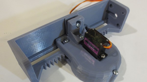
[Michael]’s actuator follows in the footstep of other designs based on a rack-and-pinion gear such as this one featured on these pages, but he approached the design problem from the perspective of a mechanical engineer. The design incorporated several compliant features to be tolerant of variances between 3D printers (and slicer, and filament, etc.) Improving the odds of a successful print and therefore successful projects. Beginners learning to design for 3D printing (and even some veterans) would find his design tips document well worth the few minutes of reading time.

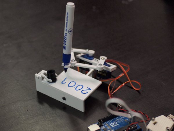
Another useful feature of his actuator design is the 20mm x 20mm screw mounting system. Visible on either end of the output slider, it allows mixing and matching from a set of accessories to be bolted on this actuator. He is already off and running down this path and is facing the challenge of having too many things to share while keeping them all organized and usable by everyone.

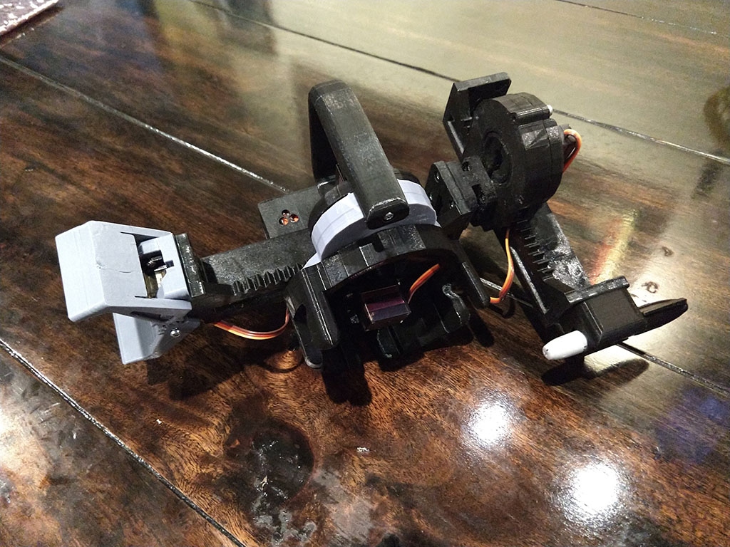
The flexible construction system allows him to realize different ideas within the modular system. He brought one item (a variant of his Mug-O-Matic) to the Hackaday + Tindie Meetup at Bay Area Maker Faire, and we’re sure there will be more. And given the thoughtful design and extensive documentation of his project, we expect to see his linear servos adopted by others and appear in other contexts as well.

This isn’t the only linear actuator we’ve come across. It isn’t even the only winning linear actuator of our Robotics Module Challenge, but the other one is focused on meeting different constraints like compactness. They are different tools for different needs – and all worthy additions to our toolbox of mechanical solutions.

Simulating VR Obstacles With Wheelchair Brakes

[Joey Campbell] is studying for his PhD at the Bristol Interaction and Graphics Lab, focusing on the interplay between real and virtual objects within the realm of exergaming–“gamercising” where physical motion and effort drives the game. The goal is to make the physical effort seem to correspond with what’s seen on the headset.

[Joey] set up a test rig where an exercise bike’s gears were adjusted based on the terrain encountered, seeking to find out if that realism inspired a greater feeling of immersion. He also provided some test subjects a HUD with their heart rate and other stats, to see if that encouraged gamers to exercise more.

In his current project, [Joey] has equipped a wheelchair with a pair of Arduino-controlled servos that squeeze the brakes to simulate an obstacle. In the VR realm, a player pushes the wheelchair toward a virtual block and the brakes engage, requiring the player push harder to bypass the obstacle.

One imagines the possibilities of games designed for specifically for wheelchairs. The Eyedrivomatic wheelchair that won the 2015 Hackaday Prize sounds perfect for the job!

Continue reading “Simulating VR Obstacles With Wheelchair Brakes”

El Cheapo Electric Screwdriver

If you have a few hobby servos lying around, here’s a hack that let’s you recycle them and put them to good use. [Kedar Nimbalkar] took a micro servo and converted it into an electric screwdriver. It is simple enough to deserve a short video showing how he did it.

He starts by opening up a 9G micro servo and removing the electronics. All that’s needed is the DC motor and the gears. The two motor wires go directly to the battery via a polarity reversal switch to allow the motor to turn in both directions. The servo horn is cut to size so that it is a tight fit inside the screwdriver socket. A liberal amount of glue is used to make sure it stays in place. The horn is then attached to the modified servo, ready to take interchangeable bits. One last mod before closing up the servo is to convert it to continuous rotation by cutting off the stopper in the drive gear.

He built the power supply from scratch, using a 18650 Li-Po battery, a 5V USB charger, a DPDT switch to allow direction control and a push button to actuate the screw driver. A pair of LED’s connected back to back serve as direction indicators as well as some local illumination.

There’s lot’s of scope to improvise and do everything differently, but the basic premise of using unused servos for a handy electric screwdriver is pretty neat.

Continue reading “El Cheapo Electric Screwdriver”

Spline Thieving Makes Hobby Servos Even More Useful

For years the proprietary spline pattern of rc servos has been a dealbreaker for hobbyists who want to add custom shafts and gears to their servos. First, different servo sizes have different spline sizes, and each vendor equips their servos with different patterns. True, some special vendors sell custom gears that mate to these patterns, but, overall, the hard-to-replicate pattern has severely limited the output options for servos.

This pattern didn’t deter [JB], however. With some clever CAD skills, and two working implementations, he’s demonstrated that these spline patterns can be (1) harvested and (2) added into custom components, opening a new suite of design opportunities involving servos.

To capture the spline, [JB] imports an image into Solidworks, and traces the pattern on a properly scaled image. From there, he can embed this pattern directly into a physical model for fabrication.

To make parts that preserve this pattern, [JB] has two options. With his FormLabs printer, he can print components that already have the pattern feature, allowing him to press-fit custom links directly onto servos. Alternatively, for a sturdier component, he presents the milling method. With this technique, he drills a circle of bolt holes onto the desired output shaft and then mills out the center. From here, the shaft can also be directly pressed onto the servo spline where each spline groove fits snugly into the edge of the previously-drilled holes.

So, how well do they work? According to [JB] he’s actually managed to do some damage to himself before damaging to the 3D-printed part while trying to strip the pattern. The end-goal is to insert these shafts into transmissions for a miniature combat robot, another one of [JB’s] projects which is well-underway. Until then, we’re looking forward to seeing more servos tightly-integrated into upcoming projects.

Web Controlled Servo From A BeagleBone Black

bbb_servo

[Babak] created an in-depth tutorial on how he got his BeagleBone Black to control a servo from a web browser.

[Babak] configured a pin on his BeagleBone Black (BBB) as a PWM line and connected it to the control line on a micro hobby servo. The BBB is running a Node.js web server that displays a simple web page to control the servo. The browser sends a WebSocket request to a small WebSocket node server also running on the BBB that then writes the appropriate PWM value to the pin connected to the servo.

The code for node WebSocket server and web server can be found on his GitHub page. There is also a small node library to control PWM lines on the BBB. Though the end result is simple, controlling the servo can be done from any browser that can make a network connection to the BeagleBone Black. Check out the video after the jump for a description and demonstration.

Continue reading “Web Controlled Servo From A BeagleBone Black”

A Clock That Plots Time

[Johannes] just sent us a tip about his small plotter that plots out the current time.

[Johannes] small clock plotter uses a dry wipe pen to write out the time on a small piece of dry erase board. The design is Made of three small 9g servos, with one to lift the pen off the writing surface and the other two to control a pair of connected jointed arms for the x and y-axis.

The little robot painstakingly wipes away the previous time before scrawling the current time in its place (with minute accuracy).

[Johannes] had hackability in mind when creating this project, making sure to keep to standard parts and making the code and design files available. The hardware for the build can be laser cut or 3D printed. The Arduino sketch can be found on GitHub and the design files can be found on Thingiverse. There are more detailed build instructions on Nuremberg’s FabLab page (translated).  Continue reading “A Clock That Plots Time”

glue stick linear actuator

Glue Stick + Servo = Linear Actuator

What do you get when you cross a glue stick with a hobby servo motor? A linear actuator, of course! Although this could be done with other household implements, the form factor of this glue stick seems perfectly suited to sit on top of a servo horn.

The servo, as you might have guessed, has to be converted to rotate fully instead of the 180 degrees or so that is typical of these types of motors. The trick to this, and what really makes it shine in our eyes, is that instead of attaching two resistors in a normal continuous rotation mod, the potentiometer is used on the glue stick allowing for position feedback.

The resulting force from this gear-reduced actuator is quite impressive, giving an “err” (over 3 Kilograms) on the scale used for testing. [Gareth] or [Chiprobot] gives a great tutorial of how to make one of these after the break, but if you’d rather just see it in action, skip to around 8:20! Continue reading “Glue Stick + Servo = Linear Actuator”