No matter how excited you are to dive headfirst into the “Internet of Things”, you’ve got to admit that the effort and expense of going full-on Jetsons is a bit off-putting. To smarten up your home you’ve generally got to buy all new products (and hope they’re all compatible) or stick janky after-market sensors on the gear you’ve already got (and still hope they’re all compatible). But what if there was a cheap and easy way to keep tabs on all your existing stuff? The answer may lie in Cold War era surveillance technology.
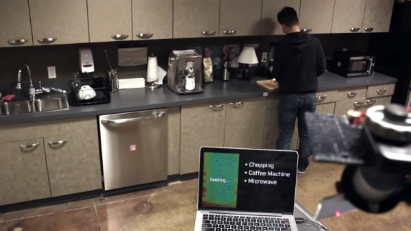
 As if the IoT wasn’t already Orwellian enough, Vibrosight is a project that leverages a classic KGB spy trick to keep tabs on what’s going on inside your home. Developed by [Yang Zhang], [Gierad Laput] and [Chris Harrison], the project uses retro-reflective stickers and a scanning laser to detect vibrations over a wide area. With this optical “stethoscope”, the system can glean all kinds of information; from how long you’ve been cooking something in the microwave to whether or not you washed your hands.
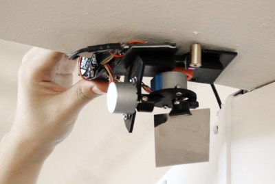
The project takes its inspiration from the optical eavesdropping system developed by Léon Theremin in the late 1940’s. By bouncing a beam of light off of a window, Theremin’s gadget was able to detect what people inside the room were saying from a distance. The same idea is applied here, except now it uses an automated laser scanner and machine learning to turn detected vibrations into useful information that can be plugged into a home automation system.
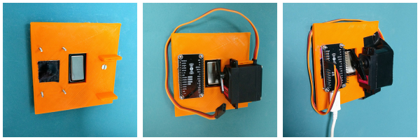
For Vibrosight to “listen” to objects, the user needs to place retro-reflective tags on whatever they want to include in the system. The laser will periodically scan around the room looking for these tags. Once the laser finds a new tag, will add it to a running list of targets to keeps an eye on. From there Vibrosight is able to take careful vibration measurements which can provide all sorts of information. In the video after the break, Vibrosight is shown differentiating between walking, jogging, and running on a treadmill and determining what kind of hand tools are being used on a workbench. The team even envisions a future where Vibrosight-ready devices would “hum” their IP address or other identifying information to make device setup easier.
If all this talk of remote espionage at a distance has caught your interest, we’ve covered Theremin’s unique surveillance creations in the past, and even a way to jam them if you’re trying to stay under the radar.
Continue reading “Vibrosight Hears When You Are Sleeping. It Knows When You’re Awake.” →