For the first in a series of posts describing how to make a PCB, we’re going with Eagle. Eagle CAD has been around since the days of DOS, and has received numerous updates over the years. Until KiCad started getting good a few years ago, Eagle CAD was the de facto standard PCB design software for hobbyist projects. Sparkfun uses it, Adafruit uses it, and Dangerous Prototypes uses it. The reason for Eagle’s dominance in a market where people don’t want to pay for software is the free, non-commercial and educational licenses. These free licenses give you the ability to build a board big enough and complex enough for 90% of hobbyist projects.
Of course, it should be mentioned that Eagle was recently acquired by Autodesk. The free licenses will remain, and right now, it seems obvious Eagle will become Autodesk’s pro-level circuit and board design software.
Personally, I learned PCB design on Eagle. After a few years, I quickly learned how limited even the professional version of Eagle was. At that point, the only option was to learn KiCad. Now that Eagle is in the hands of Autodesk, and I am very confident Eagle is about to get really, really good, I no longer have the desire to learn KiCad.
With the introduction out of the way, let’s get down to making a PCB in Eagle.
A few years ago, I wrote a few columns titled Making A Thing. These columns were a tutorial of sorts for several different 3D modeling programs. This column wasn’t meant to be a complete guide to modeling an object in OpenSCAD or SolidWorks, it was just step-by-step instructions on how to make one specific thing with one specific piece of software.
More than a few people in the Hackaday community found this column useful or at the very least an interesting pedagogical device. When starting out with any kind of productivity software, you don’t need to know how to do everything, you just need to know how to do the most common tasks.
Since the Making A Thing column was so popular, I felt it was time to revive this idea with another design task we often face. As you have already guessed, we’re going to be making printed circuit boards. Continuing the unique tutorial format created in the previous iteration of this column, Making a PCB will build one specific circuit in multiple EDA suites.
The Circuit
The entire concept of demonstrating how to build one thing in a specific software package necessitates a model thing. Before I even begin writing the first Making A PCB column, I need to design something that’s sufficiently complex but still relatively simple, and something that’s hopefully somewhat useful. Breakout boards are extremely simple, perhaps too much. In the course of these programs, I’ll need to demonstrate how to make a part in each specific software suite, so fewer pins are better.
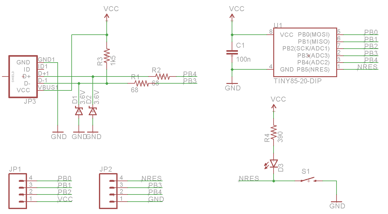
Lacking any creativity of my own, I’ve settled on a very small ATtiny85 Arduino derivative from Tim a.k.a. [cpldcpu]. Tim’s Nanite 85 is an exceptionally small Arduino-compatible board based on the ATtiny85, complete with a USB port, LED, and a few pins of I/O. It’s simple but sufficiently complex to give an introduction to a PCB design suite.
I’m not going to outright copy Tim’s Nanite 85, though. It’s much clearer if parts aren’t stacked on top of each other, and I’d like to give myself a little breathing room on the layout. I’ve redesigned the circuit of the Nanite 85 to use mostly through-hole parts on a slightly larger board. I’m calling my version the Nanite Wesley, and if you get that reference, thumbs up for you.
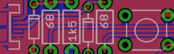
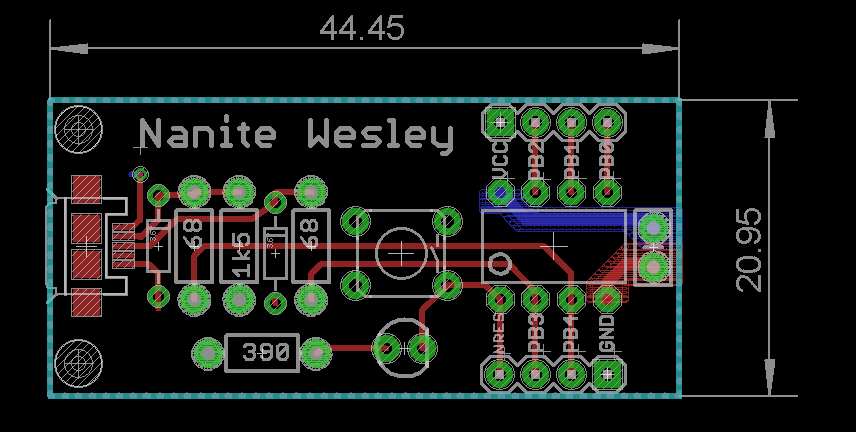
The schematic for the Nanite WesleyThe Nanite Wesley board. Copper pours not shown
Is this how a board should be laid out? No, absolutely not. I could probably do this as a single-layer board. This is a very inefficient layout, and I like rounded corners on my boards. It’s good enough, though, and it works. This is meant to be a tutorial on how to use a PCB design package, not a tutorial on how to design a PCB. Your criticisms in this regard are noted and ignored.
What These Tutorials Will Consist Of
You cannot use a PCB design package until you know how to make a part. Yes, Eagle has wonderful libraries for almost everything you can imagine, KiCad has plenty of parts on the Internet, and if you’re using a cloud-based PCB software, almost everything will be provided for you. If you make a PCB, eventually you’ll have to make your own part, though, and each tutorial will begin with making a DIP-8 ATtiny85. Everything else on this board is a jellybean part. Either way, the process of making a part and package for a Zener is the same as making one for a microcontroller.
The next part of the tutorial will consist of schematic capture. This means placing the parts in the schematic, drawing wires between the pins and pads, and naming them. From there, it’s time to actually make a board, and this means dropping the parts down, putting traces between all the pins, doing the board outline, pouring copper, and mechanical considerations.
With the schematic and board designed, it will be time to send it off to a fab house. For Eagle and KiCad, this is easy; OSHpark accepts Eagle .brd and KiCad .pcb files, but this is cheating. We’re going to use CAM to generate real Gerber files. If you make enough PCBs, you’ll have to learn it eventually.
Caveats and Poor Design
There are a lot of things that go into making a ‘proper’ PCB, including isolation, direct traces to decoupling capacitors, making sure pixies don’t go around sharp corners and a thousand other items that won’t be discussed in these tutorials. There’s a reason I won’t be discussing this. This is a guide on how to use a PCB design tool, not how to design a PCB.
What else should I do?
As you can probably guess from the schematic above, the first PCB software I’m going to cover is Eagle. KiCad is on the list, as is Fritzing, Altium CircuitMaker, and OrCAD. In the interests of putting PCB design in a historical context, I have a copy of AutoTRAX and an old DOS machine. I’ll also be covering a few of the cloud-only design tools such as Upverter.
That’s enough software suites to get started, but as with the Making A Thing series, I’m going to be looking for suggestions from the peanut gallery. I can’t change the circuit I’m making, as that’s the entire point of this series, but I am looking for suggestions on other tools to cover. What else can I do? Want me to grab a piece of copper clad board, sticker overlays, and some photostatic film? I can do that. Are you at a web-based EDA startup, and want some free advertising? Leave a note in the comments.
Thanks to our efforts to slowly improve the backend of Hackaday, you’ll be able to access all the Making A PCB In Everything posts from the series list below.
Practically any combination of motor and gearbox can be mathematically arranged to fit all sorts of problems. You could lift a crane with a pager motor, it just might take a few hundred years. However, figuring out exactly what ratio you need can feel bit backwards the first time you have to do it.
A gear is nothing more than a clever way to make two circles rotate in concert with each other as if they were perfectly joined at their circumferences. Rather than relying on the friction between two rotating disks in contact, the designer instead relies on the strength of a gear tooth as the factor limiting the amount of torque that can be applied to the gear.
Everything is in gearing is neatly proportional. As long as your point of reference is correct, and some other stuff. Uh, it gets easier with practice.
Now as my physics professors taught me to do, let’s skip the semantics and spare ourselves some pedantics. Let us assume that all gears have a constant velocity when you’ve averaged it all out. Sure there is a perceptible difference between a perfect involute and a primitive lantern gear, but for the sake of discussion it doesn’t matter at all. Especially if you’re just going to 3D print the thing. Let’s say that they’re sitting on perfect bearings and friction isn’t a thing unless we make it so. Also we’ll go ahead and make them perfectly aligned, depthed, and toleranced.
Typically, a gearbox is used for two things. You have a smaller torque that you’d like to make into a bigger one or you have one rotational velocity that you’d like to exchange for another. Typically torque is represented with a capital or lowercase Tau (Ττ) and rotational velocity likes to have a lowercase omega (ω). It also doesn’t matter at all; it just makes your equations look cooler.
Now a lot of tutorials like to start with the idea of rolling a smaller circle against a bigger one. If the smaller circle is a third as large as the big one, it will take three rotations of the small circle to make the big one rotate twice. However, it is my opinion that thinking it in terms of the force applied allows a designer to think about the gearing more effectively.
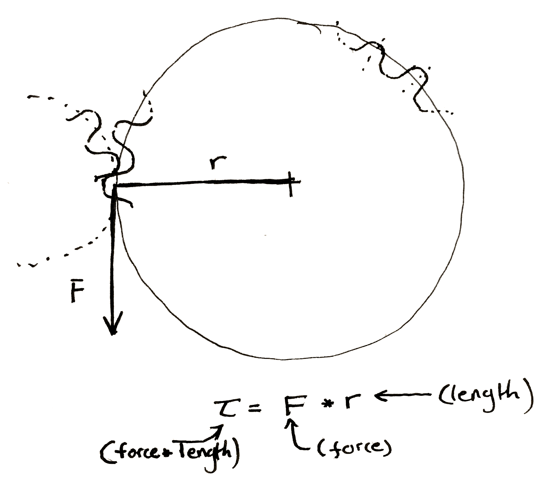
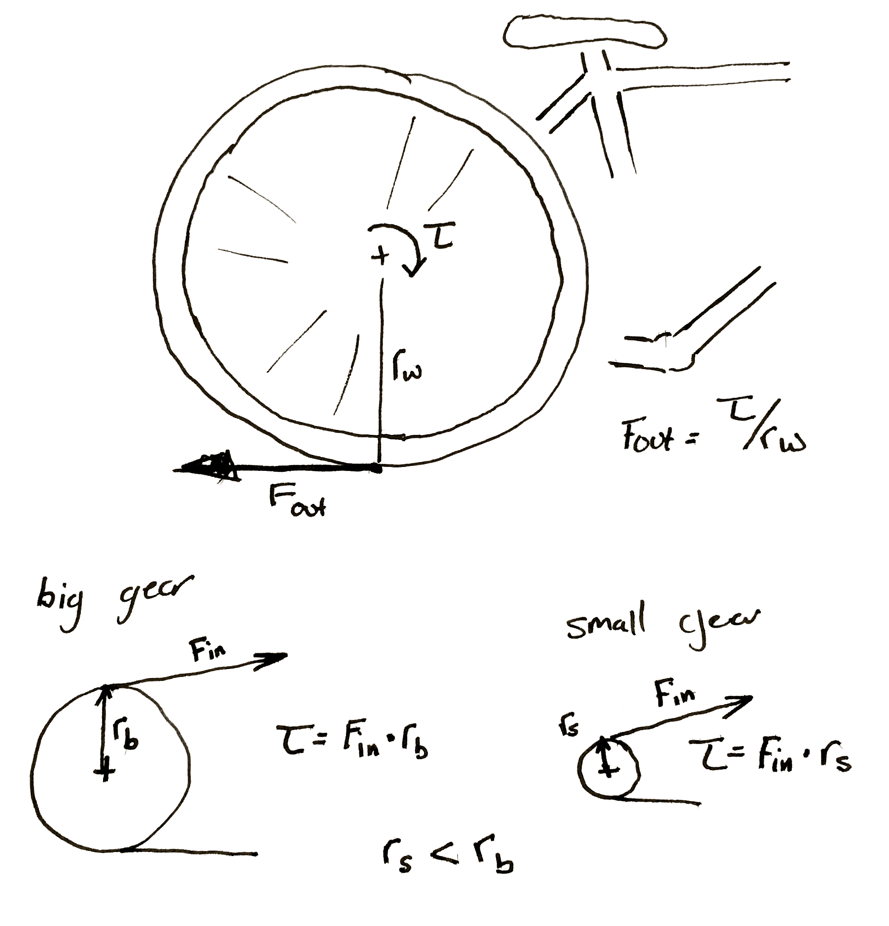
If the friction between the two surfaces of the circle is perfect, then any force applied tangentially to one of the circles will result in a perfectly perpendicular and equal force to the other circle at the point of contact between the two. Midway through writing the preceding sentence I began to understand why textbooks are so abstruse, so I also drew a picture. This results in two equations.
Now, when you have a force perpendicular to the line drawn to describe the radius, the equation for torque becomes really simple.
Multiply the length of the “lever arm”, “radius”, etc. by the force to get the preceding equations. Make sure to include the units.
You should end up force-unit * length-unit. Since I usually work in smaller gears I like to use N * mm. American websites typically use oz-in to rate motors. It is technically ozf-in (ounce-force), but the US customary system has a fetish for obtuseness.
We can make some observations. The smaller gear always sees less torque at its center. This initially seemed a bit counter-intuitive to me. If I’m using a cheater bar to turn a bolt the longer I make the bar the more torque I can put on the bolt. So if I touch the outside of a really large gear I should be seeing a ton of torque at the center of a small gear rotating along with it. However, as we mentioned before, any torque applied on the outside of the larger gear is seen equal and tangential on the smaller. It’s as if you’re touching the outside of the small gear. The torque has to be smaller.
This is why you have to pedal so much harder when the rear sprocket on a bicycle gets smaller. Each time you make the sprocket smaller you shrink the torque input into the wheel. If the perpendicular output where the wheel hits the ground is <input from the small gear> / <radius of the wheel> then it’s obvious why this happens.
Hopefully my diagram doesn’t win a prize for awfulness. Then again, an award is an award. Remember that the bicycle wheel and its input gear are rigidly attached to each other.
It’s also important to note that any time you increase the torque, the speed of the gears slow by the same proportion. If you need 60 N*m out of a motor that can give 20 N*m and you use a 3:1 gearbox to do it. If the motor previously ran at 30 rpm it’s now running at 10 rpm.
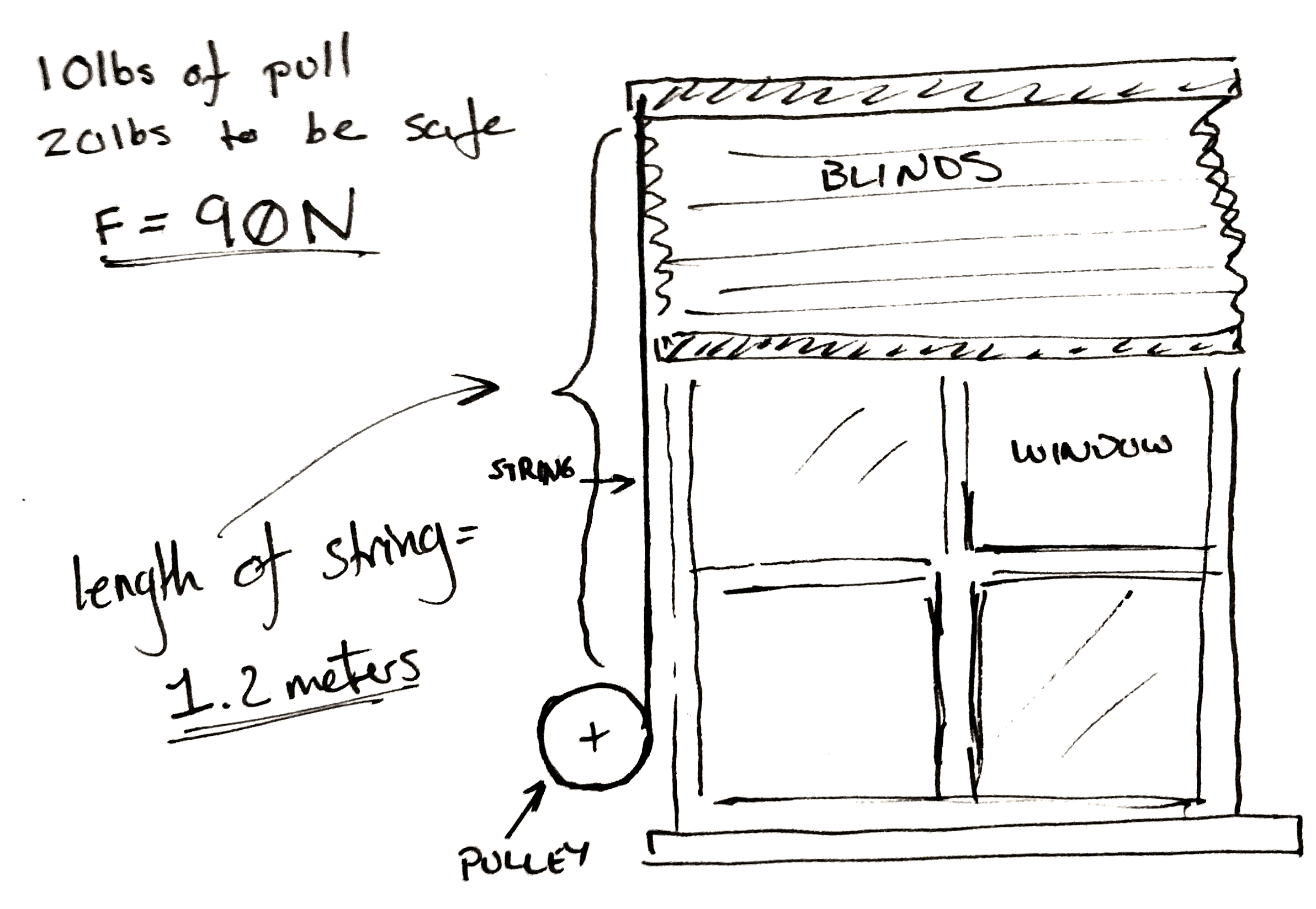
Let’s jump right into an example. Let’s say you want to make a device that automatically lifts your window blinds. You’ve got some junk and a 3D printer.
The problem set-up.
Now you’ve taken a spring scale and pulled until the shutter moves and you know you need 10 lbs. of pull to get the blinds to pull up. To make it easy on yourself you multiply this number by two so you know you need exactly 20 lbs of force to pull the curtain up. Then to make it really easy on yourself convert it all to Newtons. It’s approximately 90 N.
Now you don’t really care how fast the blinds pull up, but you go ahead and pull them up yourself. You get the feeling that the blinds won’t appreciate being lifted faster than the whole range in two seconds. You personally don’t care if takes ten seconds to, but you’d like it not to take too long.
You also measure the length of string pulled out to raise the blinds. It’s 1.2 meters.
A classic.
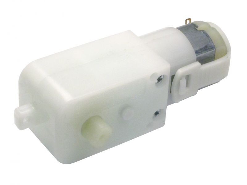
Lastly, you only have one spare power supply and a matching motor left in your entire laboratory after you followed the advice in a Hackaday article. Cursing the day the author was born, you sullenly write down the last specifications. You’ve got one of those cheap GM9 gear motors. 5 V, 66 rpm, and 300 N*mm. You damn him as you think fondly of your mountain of windshield washer motors and 80 lb server rack power supplies that you tossed out.
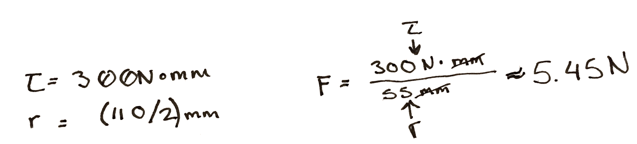
To start with, you do some experiments with a pulley. You arbitrarily pick, 3D print, and find that a 100 mm in diameter pulley seems to wind it up nicely by hand. By the end of the winding the outside diameter of the string is 110 mm. So you use the torque equations above. You find that at the end of the rotation, if you attach the motor directly, there is only 5.45 N of force being applied to the string. Not nearly enough.
Hrm..
So, since you know everything is more or less proportional, you divide 90 N / 5.45 N, and arrive at an answer of 17. So, at a minimum for every turn of the pulley you need 17 turns of the motor to get the torque needed.
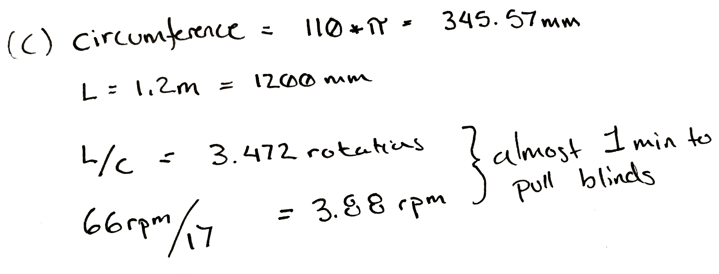
That would be okay, but it messes with our other specification. At a 17:1 ratio, it will take our 66 rpm motor pretty close to a minute to wind the blinds up.
Damn.
This is a moment for some pondering. Make a coffee. Maybe go write a relaxing comment to a Hackaday writer listing their various flaws, perceived and true, in excruciating detail.
What if you wound the string up on a closet rod? Those are only about 30 mm in diameter. You take a bit of rod and wind it up. It seems to work and since it’s wider the string only ends up adding 5 mm to the final diameter. You rework the calculation and find that in this case you only need a ratio of 6! Yes.
Now some of you who have done this before are likely gnashing your teeth, or more likely already down in the comments. Unfortunately it’s all proportional. While you only need a ratio of 6:1 now, nearly a third. You also need to rotate the pulley approximately three times as much to pull the same length of cord.
Sometimes you can’t win. In this case the only solution is to order a new motor. You look online for a bit and realize that one of the 12 V motors you threw away last week would work perfectly for this. You wouldn’t even need a gear box. You could attach it straight to the pulley. You look around your perfectly clean and orderly garage and feel empty.
However, just for fun you build a 6:1 gearbox anyway. It’s a hack after all.
Cover photo of the hilariously complicated Do Nothing Machine credit to the Joe Martin Foundation.
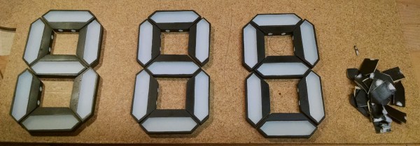
[MattB] decided to go the DIY route for some 7 segment displays that were several inches tall, but he had some particular requirements. He wanted precisely shaped elements that were as cleanly and evenly lit as possible, with no obvious points of illumination from LEDs and no visibly uneven edge lighting. To do this, he used the tools and materials he had on hand and carefully handcrafted each segment. The result is awfully close to his ideal!
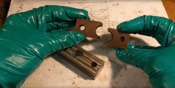
For those of us unfamiliar with the process a machinist would go through to accomplish such a thing, the video is extremely educational; it can be sobering both to see how much design work happens before anything gets powered up, and just how much time and work goes into cutting and shaping some steel into what at first glance looks like a relatively uncomplicated part.
Laser cutters are CNC power tools, which means an operator uploads a job digitally and then pushes START to let the machine do all the work while they lie back in a hammock sipping a margarita, occasionally leaping out in a panic because the sound coming from the machine changed slightly.
Like other power tools, laser cutters are built around doing one thing very well, but they require an operator’s full attention and support. The operator needs to handle all the other things that go on before, during, and after the job. It’s not too hard to get adequate results, but to get truly professional and repeatable ones takes work and experience and an attention to detail.
People often focus on success stories, but learning from failures is much more educational. In the spirit of exploring that idea, here are my favorite ways to fail at laser cutting and engraving. Not all of these are my own personal experience, but they are all someone’s personal experience.
[This Old Tony] teaches us how to make springs on a lathein this video done in the style of How It’s Made. Mixed in with snark, in his usual style, is a lot of useful information.
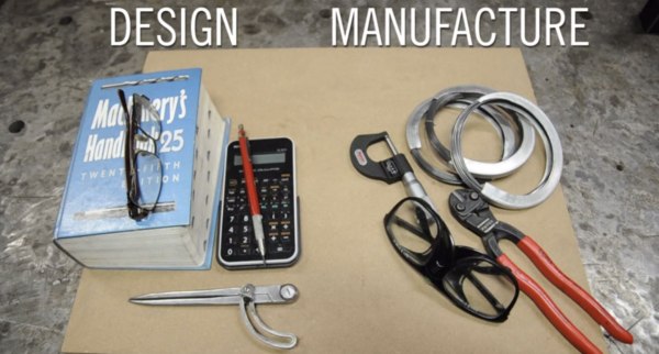
The Machinery’s Handbook certainly has all the information one would need to design the basic spring shapes, but it’s not always necessary. [Tony] points out that cheating is entirely acceptable. For example, if you need a spring that’s close to the dimensions of a standard spring, simply copy over the values from the standard spring. He explains all the terminology needed to decrypt the pages in your engineering tome of choice.
He shows the basics of winding a spring on a mandrel (or that round metal thing, if you want to use the industry term). First wind the inactive coils, then set your lathe to the desired spring pitch. Engage it as if threading, then disengage and wind the final inactive coils. A quick trip to the sander squares the ends of a standard coil spring. However, the tools can also be used to make torsion springs, or even exotic combination springs.
For a good… educational laugh, watch the whole video after the break.