If you have ever broken the ferrite core of an inductor, you’ll probably sympathize with [Oliver Mattos]. He accidentally stood on a ferrite-cored component, breaking it and rendering it useless. But utility is in the eye of the beholder, and instead of throwing it away he’s repurposed it as a chain sensor for his electric bicycle.
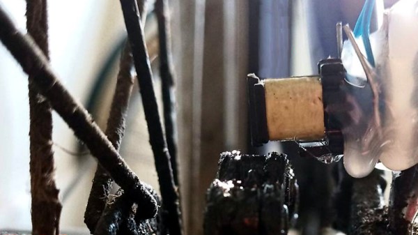
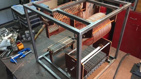
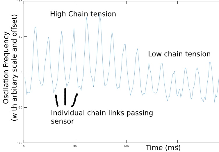 The broken inductor was positioned on the rear frame of the machine such that the chain passed through the area where the broken half of its core would once have been. As each link passes through the magnetic field it causes the inductance to change, and from this the speed, direction, and tension of the chain can be read.
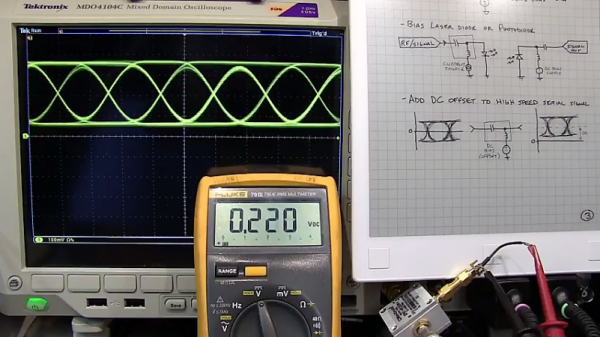
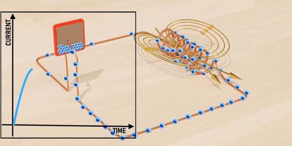
Adding a 180 nF capacitor in parallel with the inductor creates a tuned circuit, and measuring the inductance is as straightforward as firing a single pulse at it and measuring the time it takes to go negative. Chain speed can be read by sensing the change in inductance as each link passes, tension by sensing the change in inductance as the chain is closer or further away, and direction by whether the chain is slack or not. It’s an ingenious and simple solution to measuring a bicycle chain, and we like it.
A lot of bicycle measurement systems have passed our way over the years, but it’s fair to say they have been more concerned with displays than sensors.
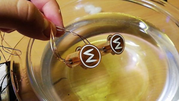
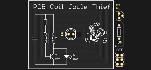
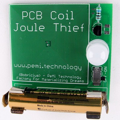 At the forefront of these experiments in PCB coil design is [bobricious], and already he’s made brushless and linear motors using only tiny copper traces on top of fiberglass. Now he’s experimenting with inductors. His latest entry to the Hackaday Prize