Most of us don’t spend that much time thinking about lightning. Every now and then we hear some miraculous news story about the man who just survived his fourth lightning strike, but aside from that lightning probably doesn’t play that large a role in your day-to-day life. Unless, that is, you work in aerospace, radio, or a surprisingly long list of other industries that have to deal with its devastating effects.
Humans have been trying to protect things from lightning since the mid-1700s, when Ben Franklin conducted his fabled kite experiment. He created the first lightning rod, an iron pole with a brass tip. He had speculated that the conductor would draw the charge out of thunderclouds, and he was correct. Since then, there haven’t exactly been leaps and bounds in the field of lightning rod design. They are still, essentially, a metal rods that attract lightning strikes and shunt the energy safely into the earth. Just as Ben Franklin first did in the 1700s, they are still installed on buildings today to protect from lightning and do a fine job of it. While this works great for most structures, like your house for example, there are certain situations where a tall metal pole just won’t cut it.
Well, at least the acronym will stay the same. It looks like black is the new blue for Windows 11, as the BSOD screen gets its first makeover in years. It’s an admittedly minor change, since the on-screen text is virtually identical to the BSOD from recent versions of Windows 10, and the new death-knell even sports the same frowny-face emoji and QR code. Really, the white-on-black color scheme is the only major difference we can see — even the acronym will stay the same. It’s not really that newsworthy, we suppose, although it does make us miss the extremely busy BSODs from back in the Windows NT days.
As the semiconductor shortage continues, manufacturers are getting desperate to procure the parts they need to make their products. And if there’s one thing as certain as death and taxes, it’s that desperation provides opportunity to criminals. A thread over on EEVBlog details an encounter one company had with an alleged scammer, who sent an unsolicited offer to them for a large number of ordinarily hard-to-find microprocessors at a good price. Wisely, the company explored the offer in some depth and found that “Brian” (the representative who contacted them) is actually named Nick Martin and, according to an article on the Electronic Resellers Association International (ERAI) website, is apparently associated with a number of fraudulent operations. Their list of allegedly fraudulent deals made by Mr. Martin stretches back to 2018 and totals over $300,000 of ill-gotten gain.
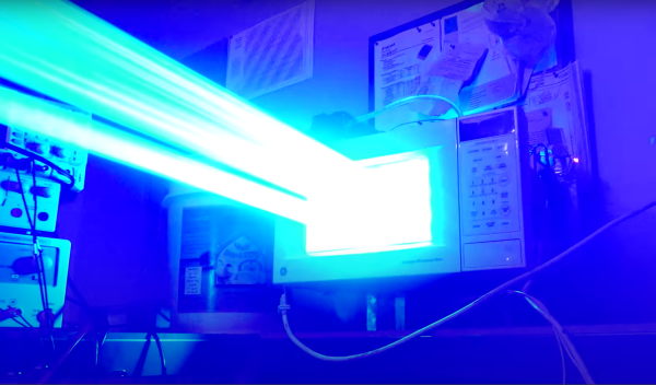
Last year, friend-of-Hackaday and laser artist Seb Lee-Delisle spent a lot of time and effort getting together an amazing interactive laser light show for the night skies of cities in the UK. Laser Light City, with powerful lasers mounted on the tops of tall buildings, was a smashing success that brought a little cheer into what was an otherwise dreadful time. But we have to admit that the videos and other materials covering Laser Light City left us wanting more — something like that, with a far-flung installation on rooftops and the ability for audience members to control it all from their phone, really needs a deeper “how it works” treatment. Thankfully, Seb has released a video that dives into the nuts and bolts of the show, including a look at ludicrously powerful lasers with beams that can still be seen in broad daylight.
You tend to think of test equipment in fairly basic terms: a multimeter, a power supply, a signal generator, and an oscilloscope. However, there are tons of highly-specialized test equipment for very specific purposes. One of these is the 8163A “lightwave multimeter” and [Signal Path] tears one part for repair in a recent video that you can see below.
If you’ve never heard of a lightwave multimeter, don’t feel bad. The instrument is a measuring system for fiber optics and, depending on the plugins installed, can manage a few tests that you’d usually use an optical power meter, a laser or light source, and some dedicated test jigs to perform. Continue reading “Lightwave Multimeter Teardown”→
Update 6/23/21: Many people have called this out as fake. When viewed at 1/4 speed, you can see the logos in the YouTube video are always full-off or full-on and never caught mid way through a scanned frame. The images may be projected from off-camera to the left, rather than by the diode behind the screen. It’s a neat idea, but on closer review the demo provided smells a bit fishy so we’ve added a “Real or Fake” tag and updated the title. Update #2: [Kanti Sharma] wrote into the tipsline apologizing for the faked video, saying that he tried to get it to work but couldn’t and then “used a phone and a lens to fake the laser”. Thanks for fessing up to this one.
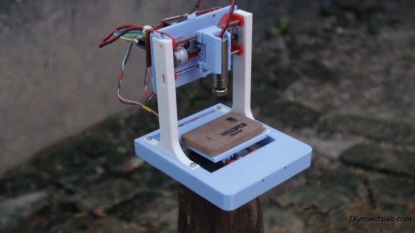
There are some times when an awesome project comes into your feed, but a language barrier intervenes as you try to follow its creator’s description. [Kanti Sharma]’s laser display appears to be a fantastic piece of work, but YouTube’s automatic translations in the video below make so little sense as to leave us Anglophones none the wiser as to what he’s saying. The principle comes across without need for translation though: he’s taken a laser diode module and is using it to create a vector scan by mounting it in the middle of a set of coils driven through beefy FETs by an Arduino. It’s an electromagnetic take on the same principle used in a CRT vector displays such as the famous Vectrex console, with the beam of electrons replaced with laser light.
It’s a technique not unlike what’s been used for years in the lighting industry, in which much larger laser displays are created with mirrors mounted on galvanometers. There must be a physical limit at which the weight of the laser slows down the movement, but if the video is to be believed it’s certainly capable of displaying graphics on a screen.
People have done a lot of things with lasers on these pages, but there have been surprisingly few vector displays using them. Here’s one from nearly a decade ago.
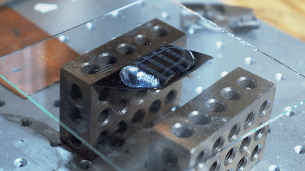
While it’s in vogue right now to name fancy new technology after Tesla, the actual inventor had plenty of his own creations that would come to bear his namesake, including Tesla coils, Tesla oscillators, Tesla turbines and even the infamous Tesla tower. One of the lesser known inventions of his is the Tesla valve, a check valve that allows flow in one direction without any moving parts, and [Huygens Optics] shows us a method of etching tiny versions of these valves into glass.
The build starts out with a fairly lengthy warning, which is standard practice when working with hydroflouric acid. The acid is needed to actually perform the etching, but it’s much more complicated than a typical etch due to the small size of the Tesla valves. He starts by mixing a buffered oxide etch, a mix of the hydroflouric acid, ammonia, and hydrochloric acid, which gives a much more even etching than any single acid alone. Similar to etching PCBs, a protective mask is needed to ensure that the etch only occurs where it’s needed. For that there are several options, each with their own benefits and downsides, but in the end [Huygens Optics] ends up with one of the smallest Tesla valves ever produced.
In fact, the valves are so small that they can only be seen with the aid of a microscope. While viewing them under the microscope he was able to test with a small drop of water to confirm that they do work as intended. And, while the valves that he is creating in this build are designed to work on liquids, [Huygens Optics] notes that the reason for making them this small was to make tiny optical components which they are known for.
A couple months back, [macona] got his hands on a 300 watt Rofin CO2 laser in an unknown condition. Unfortunately, its condition became all too known once he took a peek inside the case of the power supply and was confronted with some very toasty components. It was clear that the Magic Smoke had been released with a considerable bit of fury, the trick now was figuring out how to put it back in.
The most obvious casualty was an incinerated output inductor. His theory is that cracks in the ferrite toroid changed its magnetic properties, ultimately causing it to heat up during high frequency switching. With no active cooling, the insulation cooked off the wires and things started to really go south. Maybe. In any event, replacing it was a logical first step.
If you look closely, you may see the failed component.
Unfortunately, Rofin is out of business and replacement parts weren’t available, so [macona] had to wind it himself with a self-sourced ferrite and magnet wire. Luckily, the power supply still had one good inductor that he could compare against. After replacing the coil and a few damaged ancillary wires and connectors, it seemed like the power supply was working again. But with the laser and necessary cooling lines connected, nothing happened.
A close look at the PCB in the laser head revealed that a LM2576HVT switching regulator had exploded rather violently. Replacing it wasn’t a problem, but why did it fail to begin with? A close examination showed the output trace was shorted to ground, and further investigation uncovered a blown SMBJ13A TVS diode. Installing the new components got the startup process to proceed a bit farther, but the laser still refused to fire. Resigned to hunting for bad parts with the aid of a microscope, he was able to determine a LM2574HVN voltage regulator in the RF supply had given up the ghost. [macona] replaced it, only for it to quickly heat up and fail.
This one is slightly less obvious.
Now this was getting ridiculous. He replaced the regulator again, and this time pointed his thermal camera at the board to try and see what else was getting hot. The culprit ended up being an obsolete DS8922AM dual differential line transceiver that he had to source from an overseas seller on eBay.
After the replacement IC arrived from the other side of the planet, [macona] installed it and was finally able to punch some flaming holes with his monster laser. Surely the only thing more satisfying than burning something with a laser is burning something with a laser you spent months laboriously repairing.
We’ll just go ahead and say it right up front: we love teardowns. Ripping into old gear and seeing how engineers solved problems — or didn’t — is endlessly fascinating, even for everyday devices like printers and radios. But where teardowns really get interesting is when the target is something so odd and so specialized that you wouldn’t normally expect to get a peek at the outside, let alone tramp through its guts.
[Mads Barnkob] happened upon one such item, a Fujifilm FCR XG-1 digital radiography scanner. The once expensive and still very heavy piece of medical equipment was sort of a “digital film system” that a practitioner could use to replace the old-fashioned silver-based films used in radiography, without going all-in on a completely new digital X-ray suite. It’s a complex piece of equipment, the engineering of which yields a lot of extremely interesting details.
The video below is the third part of [Mads]’ series, where he zeroes in on the object of his desire: the machine’s photomultiplier tube. The stuff that surrounds the tube, though, is the real star, at least to us; that bent acrylic light pipe alone is worth the price of admission. Previous videos focused on the laser scanner unit inside the machine, as well as the mechatronics needed to transport the imaging plates and scan them. The video below also shows experiments with the PM tube, which when coupled with a block of scintillating plastic worked as a great radiation detector.