[Clive] had an interesting video about LED lights from Philips. You can’t buy them unless you live in Dubai. Apparently inspired by the ruler of Dubai, Sheikh Mohammad Bin Rashid Al Maktoum, who wanted more efficient and longer-lasting bulbs. The secret? A normal LED bulb uses an LED “filament” at 1 watt each. The Dubai bulbs run at about a fourth of that which means they need more LEDs to get the same amount of light, but they should last longer and operate more efficiently.
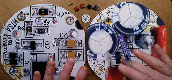
After exploring the brightness and color of different lamps, [Clive] tears one up and finds some surprises inside. The LEDs get over 200V each and the driver circuit has a lot of pairs of components, possibly to keep the size small for the high voltages involved, although it could be to improve reliability, [Clive] wasn’t sure.
By reducing the power, [Clive] was able to count that each LED strip contains 21 LEDs. He also notes some of the oddities in construction that appear to be for reliability and ease of manufacturing. We aren’t sure how that compares to the construction of conventional bulbs. The circuit includes a bridge rectifier and a linear current regulator using a MOSFET.
The bulbs cost a bit more, but if you factor in the probable long life, their total cost over time should be reasonable. Overall, it is interesting that a nice design came from what amounts to government regulation. Of course, there is a price: in exchange for the development of the bulbs, Philips has the exclusive right to make and sell the bulbs for the next several years. They expect to sell 10 million lamps by the end of 2021, although they are only available, currently, in Dubai.
Continue reading “LEDs From Dubai: The Royal Lights You Can’t Buy”

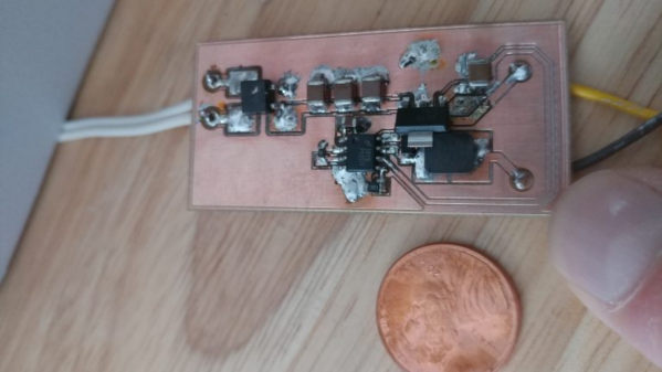
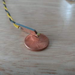 Usually, such builds are plain vanilla and not much to write in about, but [smellsofbikes] has a few tricks worth taking note of. He found a couple of high power, SMD LEDs in his parts bin. They were just slightly wider than 1.6 mm across the terminals. So he took a piece of double sided, copper clad FR4, and edge mounted the LED against one side of the PCB piece, twisting it slightly so he could solder both terminals. This works as a great heat sink for the LED while still having a very narrow profile. This was important as the replacement LED board had to fit the cylinder in which the original lamp was fitted.