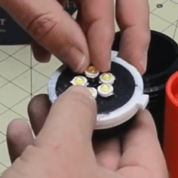
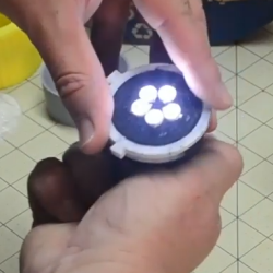
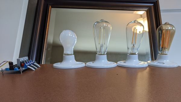
Dim Hallway Gets Lighting Upgrade

There’s nothing worse than a lightswitch that’s nowhere near where it should be, leaving you fumbling around in the dark. [supersquirrel72] had just this problem, and decided to put an Arduino to work instead.

Rather than using the original mains lighting that was poorly positioned and not enough to light the hall, instead 2 meters of white LED strip was chosen. The form factor is perfect for lighting a long, thin space – far better than running a series of seperate bulbs. The strip was rigged up to an Arduino Uno, that triggers the lights when movement is detected with a simple PIR motion sensor. After some feedback from the other occupants of the house, it was decided to tweak things further. An RTC was implemented to allow the Arduino to keep things dimmer after 9PM, so as to not wake others when making a trip to the kitchen for a midnight snack.

It’s a simple solution which brightens up the hallway nicely. We imagine this could just be the first step to a yet-more-integrated lighting solution in [supersquirrel72]’s house. Whether it’s IOT lights or something more festive, we can’t wait to see what’s next.

From Zero To LED Cube In Less Than Seven Months

We know that LED video cubes are so last year, but that doesn’t mean we don’t still love to see them. Any project that incorporates over 24,000 LEDs is bound to be impressive, after all. But the more interesting bit about [Mike Cann]’s self-contained LED cube has more to do with the process he chose to get to the finished product.

There are two ways to approach a new project, especially when you’re new to hardware hacking like [Mike] is. One is to jump in with both feet and just see what happens, for good or for ill. The other is is to ease into it with a starter project, to find out where your limitations lay and work around them gradually. [Mike Cann] wisely chose the latter approach with his LED cube project, starting with an LED sand toy. The single 64 x 64 LED panel was a bit easier to work with, and got him up to speed on the care and feeding of such hardware, as well as the code needed to drive it. The video below tells the tale of scaling that project up by a factor of six to make the cube, a process that had its share of speedbumps. Everything ended up fitting together great, though, letting [Mike] get on to the software side. That’s where this project really shines — the smartphone app running the cube is really slick, and the animations are great.

There’s clearly room for new features on [Mike]’s cube, so here’s hoping he can carve out some time to make a great build even better. For inspiration he might want to check out this side-scrolling Castlevania cube, or perhaps read up on the finer points of OpenGL for LED cubes.

Continue reading “From Zero To LED Cube In Less Than Seven Months”

A Pulse Oximeter From Very Little

Against the backdrop of a global respiratory virus pandemic, it’s likely that more than a few readers have been thinking about pulse oximeters. You may even have looked at one closely and seen that it’s little more than a device which shines light through your finger, and wondered how they work. It’s something [Giulio Pons] has done, and to show us how it’s done he’s created a working pulse oximeter of his own.

He started with an infra-red heartbeat sensor module, which is revealed as nothing more than an IR LED and a photodiode. Sampling the output from the photodiode allows measurement of heartbeat, but gives not clue as to oxygen saturation. The interesting part comes via the property of red light in that it’s transmission through flesh varies with oxygen saturation, so adding a red LED and alternately measuring from the IR and red illuminations allows a saturation figure to be derived.

Commercial pulse oximeters are pretty cheap, so many of us will no doubt simply order one from the usual sources and call it good. But it’s always interesting to know how any device works, and this project reveals something simpler than we might have expected. If pulse oximeters interest you, compare it with this one we featured a few years ago.

Blinkenlights For Your Parallel Port

Most modern equipment is connected over USB, and generally speaking we’re all the better for it. But that’s not to say there aren’t some advantages to using serial and parallel ports. For example, the slower and less complex protocols can be a bit easier to debug when devices aren’t communicating, which [Jeremy Cook] demonstrates in his latest project.

Looking to troubleshoot some communications problems he was having between his computer and CNC router, [Jeremy] came up with a handy little gadget that will allow him to visualize data passing through each pin of the parallel port in real-time. Even from across the room he can tell at a glance if communication is active, and with a keen eye, determine if he’s getting bi-directional traffic or not.

From a technical standpoint, this is a pretty simple project. The custom PCB is essentially just a pass-through, with an array of 3 mm LEDs and matching 10K resistors hanging off the data lines. But [Jeremy] found it to be an excellent excuse to brush up his KiCad skills. As he explains in the video after the break, this project certainly won’t impress the folks that do PCB design on a daily basis; but if you’re still learning the ropes, these are precisely the kind of projects you should be looking for.

Before any of you say it in the comments, we already know devices like this are available commercially for a few bucks. But that’s hardly the point. Things would be awfully slow around these parts if we disregarded any project that had a commercial alternative.

Continue reading “Blinkenlights For Your Parallel Port”

Reverse Engineering Saves Trashed LED Panels

While out riding his bike, [Hammond Pearce] came across a dumpster overflowing with large LED panels. Despite the fact that the model numbers didn’t reveal anything helpful after some online searching, he decided to pedal off with as many as he could safely carry. The COVID-19 lockdown left him with only a limited set of tools, be he still managed to crack the protocol used to control his e-waste score and document it for our reading pleasure.

Between the helpful labels on the PCB silkscreen and the advice of a friend that used to work on digital road signs, it didn’t take [Hammond] long to get a general idea of what the panels were looking for in terms of power and control. Especially once he noticed the MBI5024 shift registers dotting the board.

The next step was to take an ATmega328PB based development board and start throwing data at the panel’s input lines to see if he could elicit a response. With careful attention and some custom code, he eventually figured out that each byte of data sent down the line would control a 4 x 2 section of LEDs.

Once he had the basics down, the next step was to start expanding his code to handle things like shapes, text, and daisy-chained panels. After posting some of his work to Reddit, cyber-sleuths determined that the protocol appeared to be some variation of HUB75, which gave [Hammond] hints on what some of the other pins in the connector might be used for. He’s released all of his code online for anyone who might find it useful, but since he still doesn’t know who made these panels and why there’s really no telling how many of them are actually floating around out there.

Figuring out how to talk to an unknown or undocumented piece of hardware can be intimidating, but success stories like these are reminders of why it’s worth putting the effort in. As we’ve seen, the difference between trash and treasure is often a keen eye and a few lines of code.

Fail Of The Week: Bright Idea For LED Signs Goes Bad

Typically when we select a project for “Fail to the Week” honors, it’s because something went wrong with the technology of the project. But the tech of [Leo Fernekes]’ innovative LED sign system was never the problem; it was the realities of scaling up to production as well as the broken patent process that put a nail in this promising project’s coffin, which [Leo] sums up succinctly as “The Inventor’s Paradox” in the video below.

The idea [Leo] had a few years back was pretty smart. He noticed that there was no middle ground between cheap, pre-made LED signs and expensive programmable signboards, so he sought to fill the gap. The result was an ingenious “LED pin”, a tiny module with an RGB LED and a microcontroller along with a small number of support components. The big idea is that each pin would store its own part of a display-wide animation in flash memory. Each pin has two terminals that connect to metal cladding on either side of the board they attach to. These two conductors supply not only power but synchronization for all the pins with a low-frequency square wave. [Leo]’s method for programming the animations — using a light sensor on each pin to receive signals from a video projector — is perhaps even more ingenious than the pins themselves.

[Leo]’s idea seemed destined for greatness, but alas, the cruel realities of scaling up struck hard. Each prototype pin had a low part count, but to be manufactured economically, the entire BOM would have to be reduced to almost nothing. That means an ASIC, but the time and expense involved in tooling up for that were too much to bear. [Leo] has nothing good to say about the patent game, either, which his business partners in this venture insisted on playing. There’s plenty of detail in the video, but he sums it up with a pithy proclamation: “Patents suck.”

Watching this video, it’s hard not to feel sorry for [Leo] for all the time he spent getting the tech right only to have no feasible way to get a return on that investment. It’s a sobering tale for those of us who fancy ourselves to be inventors, and a cautionary tale about the perils of participating in a patent system that clearly operates for the benefit of the corporations rather than the solo inventor. It’s not impossible to win at this game, as our own [Bob Baddeley] shows us, but it is easy to fail.

Continue reading “Fail Of The Week: Bright Idea For LED Signs Goes Bad”

RGB Kitchen Uses Pots To Stir Up Color

Anyone who has done anything with RGB LEDs knows that their ability to display pretty much any color is somehow both the best and worst thing about them. How do you get it right? How do you make your results repeatable? [Thomas] has the answer. He dug around in the ol’ parts cupboard, found a few pots, and got to work making this stay-home stew of a project — an on-demand RGB LED color mixer.

Three cleverly color-coded potentiometers and an Arduino let [Thomas] step through 0-255 to mix various values of red, blue, and green. The shade that gets made is displayed live on a set of 10 individual NeoPixels that are laid out under a frosty diffusing panel. Each of the RGB values are also shown on an 16×2 LCD.

This is one of those projects that hits a sweet spot of being simple, useful, and fun. It’s even nice-looking and compact. What more could you want from a project cobbled together from ingredients on hand? [Thomas] is even giving away the code recipe.

Once you dial in your ideal colors, why not make a gesture-controlled lamp?