DIY Linear Tubular Motor Does Precise Slides

We’ve seen plenty of motor projects, but [Jeremy]’s DIY Tubular Linear Motor is a really neat variety of stepper motor in a format we certainly don’t see every day. It started as a design experiment in making a DIY reduced noise, gearless actuator and you can see the result here.

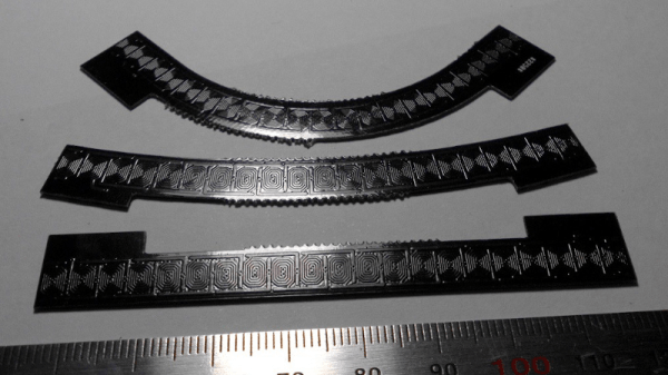
Here’s how it works: the cylindrical section contains permanent magnets, and it slides back and forth through the center of a row of coils depending on how those coils are energized. In a way, it’s what one would get by unrolling a typical rotary stepper motor. The result is a gearless (and very quiet) linear actuator that controls like a stepper motor.

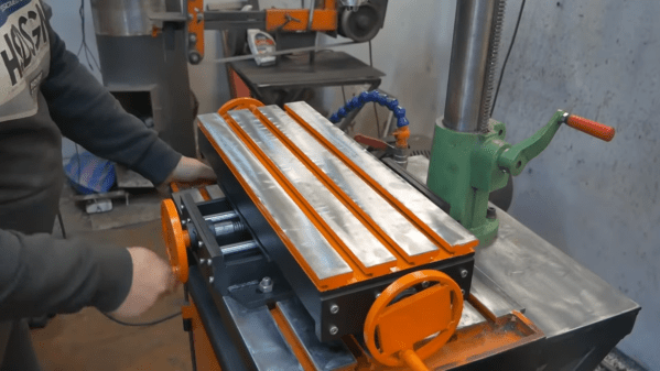
While a tubular linear motor is at its heart a pretty straightforward concept, [Jeremy] found very little information on how to actually go about making one from scratch. [Jeremy] acknowledges he’s no expert when it comes to motor design or assembly, but he didn’t let that stop him from iterating on the concept (which included figuring out optimal coil design and magnet spacing and orientation) until he was satisfied. We love to see this kind of learning process centered around exploring an idea.

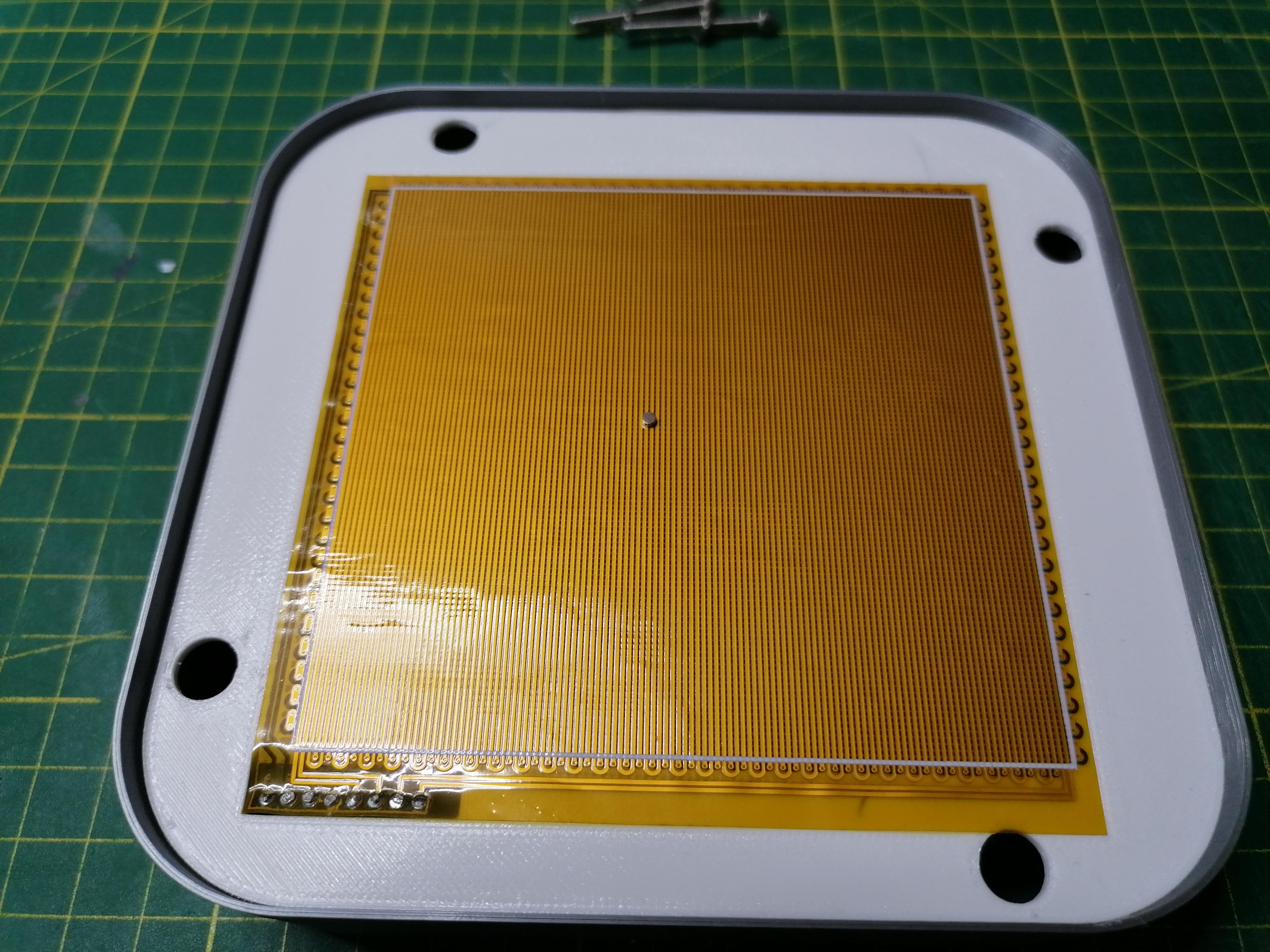
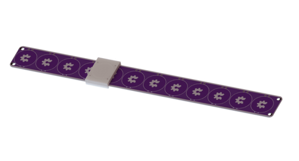
We’ve seen DIY linear motors embedded in PCBs and even seen them pressed into service as model train tracks, but this is the first time we can recall seeing a tubular format.

Watch it in action in the short video embedded below, and dive into the project log that describes how it works for added detail.

Continue reading “DIY Linear Tubular Motor Does Precise Slides”

A display based on magnetic viewing film

Moving Magnet Draws Stylish Shapes On Flexible Film

[Moritz v. Sivers] has a knack for making his own displays, which are typically based on some obscure physical effect. Magnetic viewing films, those thin plastic sheets that change color in response to a magnetic field, are his latest area of interest, as you can see in his Magnetic Kinetic Art Display.

The overall idea of the display is similar to a kinetic sand art table, in which a ball traces out shapes in a pile of sand. In [Moritz]’s project, the magnetic viewing film is the sand, and a 2 mm diameter magnet is the ball. The magnet is moved along the film by two sets of coils embedded inside a flex PCB mounted just below the film. One set of coils, on the top layer of the PCB, moves the magnet in the x direction, while a second set on the bottom layer moves it in the y direction.

A flex PCB with coils on both sides
The flex PCB is small, but carries lots of windings

[Moritz] used a flex PCB not because it had to be bendy, but to keep the two sets of coils as close together in the z direction as possible. This helps to avoid a big difference in strength between the two directions. To drive the coils, he used a pair of TB6612FNG stepper motor drivers, controlled by a Wemos D1 Mini.

The housing was 3D printed mostly from PLA, but with a few bits done in PETG. This was for structural rigidity as well as thermal performance — the coils can carry up to two amps and get pretty warm as a result.

The video, embedded below, shows some of the shapes that can be drawn: squares, spirals and even digits to turn the display into a clock. [Moritz] got the PCB coil idea from a project by [bobricius], and cleverly extended it into a useful product. It’s not the first time [Moritz] used magnetic viewing film to make a clock, either.

Continue reading “Moving Magnet Draws Stylish Shapes On Flexible Film”

linear motor pcb model railroad track

PCB Linear Motors For Model Trains

Modeling a railroad is hard. Railroads are large, linear pieces of civil engineering. So many modelers are drawn to the smallest scale they can use. Recently a new scale, named T, at 1:450 has been pushing this barrier. But fitting a reliable mechanical drive mechanism and MCU board in a package this size is a challenge. In practice, even more of a problem is getting reliable electrical contact through a metal wheel on metal track (about the worst possible design for a contact).T scale electric locomotive held on a human finger

T always seemed to us a long way out on the bleeding edge. But all that may have changed. In a recent Hackaday.io writeup, author [Martin] describes a PCB technology based linear motor system to externally drive T scale locomotives.

The system uses 4mm planar coils. The underside of the PCB has another coil, so the effective pitch is 2mm. With microstepping, a step of 0.25mm is possible, and trains run smoothly. Current is 3-400mA. Continue reading “PCB Linear Motors For Model Trains”

A row of electromagnetic coils fastened to a metal track

Propel Paper Planes, Bisect Sausages With Electromagnets

Are you still launching paper airplanes using your hands? That’s like a baby’s toy! [Tom Stanton] and his homebrew electromagnetic rail launcher are sure to bring your paper airplane game into the 21st century.

To be fair, these kinds of linear motors can be used for more than just launching paper airplanes, and can already be found in niche industrial applications, mass transportation systems and roller coasters. And, yes, the potential to leverage electromagnetism in the theater of war is also being vigorously explored by many of the world’s superpowers in the form of Gauss rifles and railguns. In the meantime, the video (after the break) proves that it’s entirely possible to build a rudimentary yet effective linear motor in your makerspace, using relatively basic components and fundamental physics.

In short, these launch systems use electromagnetism and well timed electronics to propel a mass of magnetic material down a straight (or sometimes curved) track. Multiple pairs of coils are placed along the track, with each pair subsequently energized by high current as the payload approaches. By using many coils in succession, the mass and its payload can be accelerated to high speed.

While a homemade rail launcher is unlikely to turn the tides of war, [Tom Stanton] explores their lethal potential with an experiment involving high-speed video and supermarket sausages, with gruesome results.

If you’re looking for more, why not check out our our previous coverage on electromagnetic weaponry?

Continue reading “Propel Paper Planes, Bisect Sausages With Electromagnets”

Scratch-Built XY Table Gets The Job Done

Unless you have one large pile of cash to burn through, properly equipping a workshop can take years of burning through little piles of cash. Whether to save a bit of cash or simply for the challenge, [Workshop from Scratch] is doing exactly what his channel name suggests, and his latest project is a XY table. (Video, embedded below.)

A XY table, or cross table, allows a workpiece to be translated in two dimensions, usually on a drill press or milling machine. On a drill press they make repetitive task like drilling a series of holes simpler and quicker. [Workshop from Scratch] built most of the frame with steel flat bar, and the moving parts run on ground steel rods with linear bearings. Lead screws with hand wheels are used to translate the table.

A machine like this requires the opposing plates of each table to be perfectly aligned, which [Workshop from Scratch] achieved by spot welding the matching plates together and drilling them in one operation. He also added T-slot top surface, created by welding wide flat bar on top of narrower flat bar.

With the lack of dials, it doesn’t look like it’s meant for precision work, but we would still be interested to know how repeatable the lead screw positioning is. Regardless, it’s still a useful addition to the shop.

[Workshop from Scratch] is building a rather impressive collection of DIY tools, including a magnetic vise (that he already used with the XY table), magnetic drill press and a hydraulic lift table. We look forward to seeing what’s next on the list. Continue reading “Scratch-Built XY Table Gets The Job Done”

Circular Linear Motor Becomes A Micro Motor Raceway

Over on Hackaday.io we have a lot of people playing around with the possibilities presented by cheap printed circuit boards. Whether that means making a quadcopter from fiberglass or a speaker from etched copper, we’ve seen just about everything. Now, finally, we have a miniature magnetic racetrack. It’s an ant highway, or a linear motor wrapped around into a circle. Or a tiny-scale model railroad. Either way it’s very, very cool.

The ant highway comes from [bobricius], one of the many makers tinkering around with coils and traces. This time he’s built a ten centimeter square board that is, effectively, a linear motor. It’s a three-phase motor made out of PCB coils, with a small magnetic ‘car’ that’s pushed forward. These coils are controlled by an ATtiny10 and a trio of MOSFETs. Wrap that linear motor into a circle and you have a neat little circular track that’s the smallest model car raceway you’ve ever seen.

As with all of [bobricius]’ circuit boards, this one demands a video, and that’s available below. This is an interesting bit of technology, and it’s more than just a raceway for tiny magnetic cars. This could be the beginnings of an analog clock with a digital heart, or the start of the smallest model train layout you’ve ever seen. There’s impressive work being done with PCB motors now that printed circuit boards are so cheap, and we can’t wait to see what’s next.

A quick Hackaday search will reveal [bobricius] as a prolific source of projects whose work we’ve featured multiple times. Favorites include a brushless PCB motor, and an FR4 cell phone.

Continue reading “Circular Linear Motor Becomes A Micro Motor Raceway”

PCBs As Linear Motors

PCBs are exceptionally cheap now, and that means everyone gets to experiment with the careful application of copper traces on a fiberglass substrate. For his Hackaday Prize entry, [Carl] is putting coils on a PCB. What can you do with that? Build a motor, obviously. This isn’t any motor, though: it’s a linear motor. If you’ve ever wanted a maglev train on a PCB, this is the project for you.

This project is a slight extension of [Carl]’s other PCB motor project, the aptly named PCB Motor. For this project, [Carl] whipped up a small, circular PCB with a few very small coils embedded inside. With the addition of a bearing, a few 3D printed parts, and a few magnets, [Carl] was able to create a brushless motor that’s also a PCB. Is it powerful enough to use in a quadcopter? Probably not quite yet.

Like [Carl]’s earlier PCB motor, this linear PCB motor follows the same basic idea. The ‘track’, if you will, is simply a rectangular PCB loaded up with twelve coils, each of them using 5 mil space and trace, adding up to 140 turns. This is bigger than the coils used for the (circular) PCB motor, but that only means it can handle a bit more power.

As for the moving part of this motor, [Carl] is using a 3D printed slider with an N52 neodymium magnet embedded inside. All in all, it’s a simple device, but that’s not getting to the complexity of the drive circuit. We’re looking forward to the updates that will make this motor move, turning this into a great entry for The Hackaday Prize.