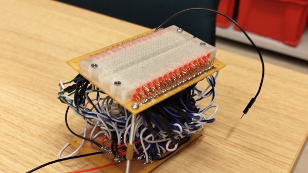
Most Hackaday readers will no doubt at some point used a solderless breadboard for prototyping. They do the job, but sometimes their layout can be inflexible and keeping track of signals can be a pain. There’s a neat idea from [rasmusviil0] which might go some way to making the humble breadboard easier to use, it’s a breadboard in which each line is coupled via an op-amp buffer to an LED. In this way it can be seen at a glance some indication of the DC voltage present.
It’s an idea reminiscent of those simple logic probes which were popular years ago, but its implementation is not entirely easy. Each circuit is simple enough, but to replicate it across all the lines in a breadboard makes for a huge amount of quad op-amp chips stuffed onto one piece of stripboard as well as a veritable forest of wires beneath the board.
The effect is of a breadboard crossed with a set of blinkenlights, and we could see that for simple digital circuits it could have some utility if not so much for higher frequency or analogue signals. Certainly it’s an experiment worth doing, and indeed it’s not the first tricked out breadboard we’ve seen.
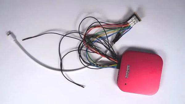
A frequent contributor to the hacker community, [stacksmashing] has prepared an excellent instructional video on reverse engineering Apple’s Lighting connector proprietary protocol. The video begins by showing how to gain physical access to the signals and hooking them up to a logic analyzer. He then notes that the handshaking uses only a single signal and proposes that Apple isn’t going to re-invent the wheel (perhaps a risky assumption). Using a ChatGPT search, obligatory these days, we learn that Dallas Semiconductor / Microchip 1-wire is probably the protocol employed.
Which embedded single-wire busses exist that encode bits with different lengths of low and high signals?
At the basic level, 1-wire and protocols like Texas Instruments SDQ operate in a similar manner. It turns out that [stacksmashing] already wrote a SDQ analyzer module for the Saleae logic analyzer. Aided by this tool, he digs deeper and learns more about the kinds of messages and their contents. For example, upon being plugged in, the host system queries the accessory’s serial number, manufacturer, model number, and product description. Finally, he introduces the CRC reverse engineering tool reveng to determine which CRC polynomial and algorithm the protocol uses to frame each packet.
Even if you have no interest in Lightning cables, this video is a great tutorial on the types of things you need to do in order to make sense of an unknown communications protocol. Gather what information you can, make some educated guesses, observe the signals, revise your guesses, and repeat. In part two, [stacksmashing] will show how to build a homemade iPhone JTAG cable.
We wrote in more detail about cracking the Lightning interface back in 2015. The Lightning interface may have been a good solution in its day, foreshadowing some of the features we now have in USB-C. But its proprietary and closed nature meant it wasn’t used outside of the Apple ecosystem. With the proliferation and capabilities of USB-C, not to mention various legislative edicts, Lightning’s days seem numbered. Is the industry finally settling on one interface? Let us know your thoughts in the comments below.
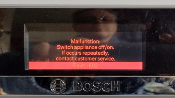
It all started with a vague error code (shown in the image above) on [nophead]’s Bosch SMS88TW01G/01 dishwasher, and it touched off a months-long repair nightmare that even involved a logic analyzer. [nophead] is normally able to handily diagnose and repair electronic appliances, but this time he had no idea what he was in for.
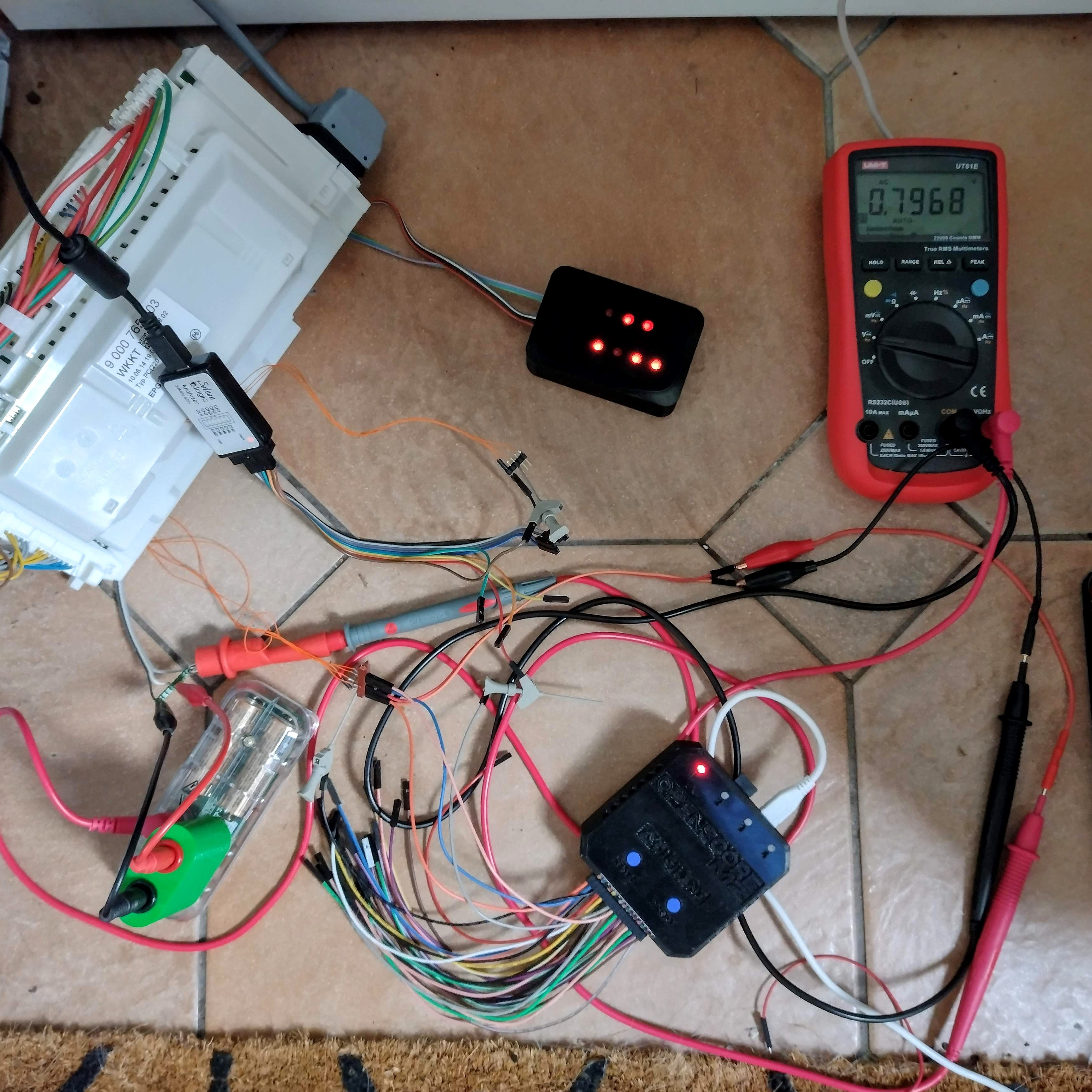
Not many dishwashers require breaking out a logic analyzer and 3D-printed custom adapters, but this one did.
Not only were three separate and unrelated faults at play (one of them misrepresented as a communications error that caused a lot of head-scratching) but to top it all off, the machine is just not very repair-friendly. The Bosch device utilized components which are not easily accessible. In the end [nophead] prevailed, but it truly was a nightmare repair of the highest order. So what went wrong?
One error appears to have been due to a manufacturing problem. While reverse-engineering the electronics in the appliance, [nophead] noticed a surface-mounted transistor that looked crooked. It was loose to the touch and fell into pieces when he attempted to desolder it. This part was responsible for switching an optical sensor, so that was one problem solved.
Another issue was a “communications error”. This actually came down to ground leakage due to a corroded and faulty heater, and to say that it was a pain to access is an understatement. Accessing this part requires the machine to be turned upside down, because the only way to get to it is by removing the base of the dishwasher, which itself requires a bizarre series of awkward and unintuitive steps to remove. Oh, and prior to turning the machine upside down, one has to purge the sump pump, which required a 3D-printed adapter… and the list goes on.
And the E02 error code, the thing that started it all? This was solved early in troubleshooting by changing a resistor value by a tiny amount. [nophead] is perfectly aware that this fix makes no sense, but perhaps it was in fact related to the ground leakage problem caused by the corroded heater. It may return to haunt the future, but in the meantime, the machine seems happy.
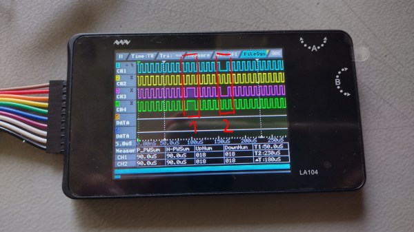
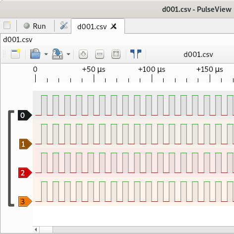
[Avian] has picked up a Miniware LA104 – a small battery-powered logic analyzer with builtin protocol decoders. Such analyzers are handy tools for when you quickly need to see what really is happening with a certain signal, and they’re cheap enough to be sacrificial when it comes to risky repairs. Sadly, he stumbled upon a peculiar problem – the analyzer would show the signal glitching every now and then, even at very low bitrates. Even more surprisingly, the glitches didn’t occur in the signal traces when exported and viewed on a laptop.
He dug into the problem, as [Avian] does. Going through the problem-ridden capture files helped him realize that the glitch would always happen when one of the signal edges would be delayed by a few microseconds relative to other signal edges — a regular occurrence when it comes to digital logic. This seems to stem from compression being used by the FPGA-powered “capture samples and send them” part of the analyzer. This bug only relates to the signal as it’s being displayed on the analyzer’s screen, and turned out that while most of this analyzer’s interface is drawn by the STM32 CPU, the trace drawing part specifically was done by the FPGA using a separate LCD interface.
It would appear Miniware didn’t do enough testing, and it’s impossible to distinguish a good signal from a faulty one when using a LA104 – arguably, the primary function of a logic analyzer. In the best of Miniware traditions, going as far as being hostile to open-source firmware at times, the FPGA bistream source code is proprietary. Thus, this bug is not something we can easily fix ourselves, unless Miniware steps up and releases a gateware update. Until then, if you bought a LA104, you can’t rely on the signal it shows on the screen.
When it comes to Miniware problems, we’ve recently covered a Miniware tweezer repair, requiring a redesign of the shell originally held together with copious amount of glue. At times, it feels like there’s something in common between glue-filled unrepairable gadgets and faulty proprietary firmware. If this bug ruins the LA104 for you, hey, at least you can reflash it to work as an electronics interfacing multitool.
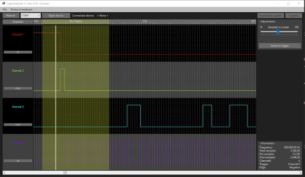
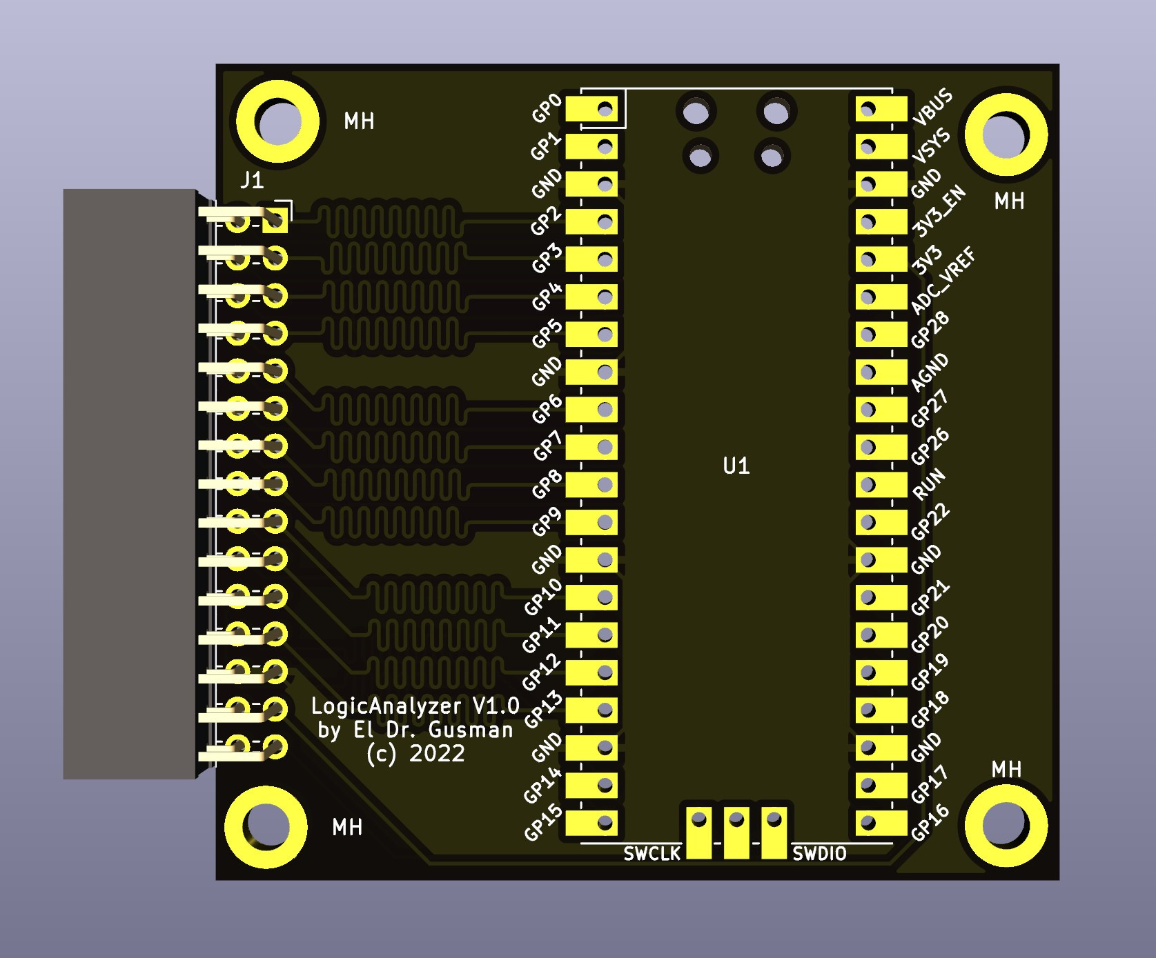
A common enough microcontroller project is to create some form of logic analyzer. In theory, it should be pretty easy: grab some digital inputs, store them, and display them. But, of course, the devil is in the details. First, you want to grab data fast, but you also need to examine the trigger in real time — hard to do in software. You may also need input conditioning circuitry unless you are satisfied with the microcontroller’s input characteristics. Finally, you need a way to dump the data for analysis. [Gusmanb] has tackled all of these problems with a simple analyzer built around the Raspberry Pi Pico.
On the front and back ends, there is an optional board that does fast level conversion. If you don’t mind measuring 3.3 V inputs, you can forego the board. On the output side, there is custom software for displaying the results. What’s really interesting, though, is what is in between.
The simple PCB is completely optional.
The Pico grabs 24 bits of data at 100 MHz and provides edge and pattern triggers. This is impressive because you need to look at the data as you store it and that eats up a few instruction cycles if you try to do it in software, dropping your maximum clock rate. So how does this project manage it?
It uses the Pico’s PIO units are auxiliary dedicated processors that aren’t very powerful, but they are very fast and deterministic. Two PIO instructions are enough to handle the work for simple cases. However, there are two PIOs and each has four separate state machines. It still takes some work, but it is easier than trying to run a CPU at a few gigahertz to get the same effect. The fast trigger mode, in particular, abuses the PIO to get maximum speed and can even work up to 200 MHz with some limitations.
If you want to try it, you can use nothing more than a Pico and a jumper wire as long as you don’t need the level conversion. The project page mentions that custom software avoids using OpenBench software, which we get, but we might have gone for Sigrok drivers to prevent having to reinvent too many wheels. The author mentions that it was easier to roll your own code than conform to a driver protocol and we get that, too. Still, the software looks nice and even has an SPI protocol analyzer. It is all open source, so if you want other protocols before the author gets to them, you could always do it yourself.
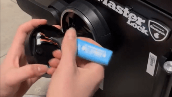
[Etienne Sellan] got one of these lovely $5 logic analyzers. As with any shiny new tool, he started looking for things to investigate with it, and his gaze fell on a Sentry Safe (produced by Master Lock). On the surface level, this keypad-equipped safe is designed decently when it comes to privilege separation. You can take the keypad board off and access its backside, but the keypad doesn’t make any decisions, it merely sends the digits to a different board embedded behind the safe’s door. The solenoid-connected board receives the PIN, verifies it, and then controls the solenoid that unlocks the safe.
[Etienne] hooked up a logic analyzer to the communication wire, which turned out to be a UART channel, and logged the keypad communication packets — both for password entry and for password change. Then, he wrote some Arduino code to send the same packets manually, which worked wonders. Bruteforcing wasn’t viable, however, due to rate limitation in the solenoid controller. Something drew his attention from there – if you want to change the password, the keypad requires you enter the factory code, unique to each safe and supplied in the instruction manual. That code entry is a separate kind of packet from the “change password” one.
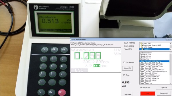
[Jure Spiler] was at a flea market and got himself a spectrophotometer — a device that measures absorbance and transmittance of light at different wavelengths. This particular model seems to be about 25 years old, and it’s controlled by a built-in keyboard and uses a graphical LCD to display collected data. That might have been acceptable when it was made, but it wasn’t enough for [Jure]. Since he wanted to plot the spectrophotometry data and be able to save it into a CSV file, hacking ensued.
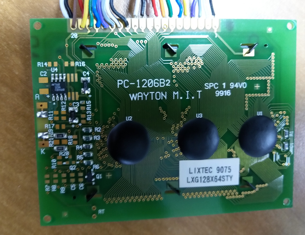
He decided to tap into the the display communication lines. This 128×64 graphical display, PC-1206B, uses a 8-bit interface, so with a 16-channel logic analyzer, he could see the data being sent to the display. He even wrote decoder software – taking CSV files from the logic analyzer and using primitive optical recognition on the decoded pixels to determine the digits being shown, and drawing a nice wavelength to absorbance graph. From there, he set out to make a standalone device sniffing the data bus and creating a stream of data he could send to a computer for storage and processing.
[Jure] stumbled into a roadblock, however, when he tried to use an Arduino for this task. Even using a sped-up GPIO library (as opposed to notoriously inefficientdigitalRead), he couldn’t get a readout frequency higher than 80 KHz – with the required IO readout rate deemed as 1 MHz, something else would be called for. We do wonder if something like RP2040 with its PIO machinery would be better for making such captures.
At that point, however, he found out that there’s undocumented serial output on one of the pins of the spectrophotometer’s expansion port, and is currently investigating that, having shelved the LCD sniffing direction. Nevertheless, this serves as yet another example for us, for those times when an LCD connection is all that we can make use of.