Hackaday Prize 2023: AC Measurements Made Easy

When working on simple DC systems, a small low-cost multimeter from the hardware store will get the job done well enough. Often they have the capability for measuring AC, but this is where cheap meters can get tripped up. Unless the waveform is a perfect sinusoid at a specific frequency, their simple algorithms won’t be able to give accurate readings like a high-quality meter will. [hesam.moshiri] took this as a design challenge, though, and built an AC multimeter to take into account some of the edge cases that come up when working with AC circuits, especially when dealing with inductive loads.

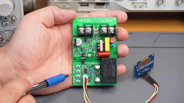
The small meter, an upgrade from a previous Arduino version that is now based on the ESP32, is capable of assessing root mean square (RMS) voltage, RMS current, active power, power factor, and energy consumption after first being calibrated using the included push buttons. Readings are given via a small OLED screen and have an accuracy rate of 0.5% or better. The board also includes modern design considerations such as galvanic isolation between the measurement side of the meter and the user interface side, each with its own isolated power supply.  The schematics and bill-of-materials are also available for anyone looking to recreate or build on this design.

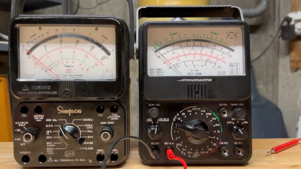
With the project built on an easily-accessible platform like the ESP32, it would be possible to use this as a base to measure other types of signals as well. Square and triangle waves, as well as signals with a large amount of harmonics or with varying frequencies, all need different measurement techniques in order to get accurate readings. Take a look at this classic multimeter to see what that entails.

Continue reading “Hackaday Prize 2023: AC Measurements Made Easy”

Digital Microscope With An On-Screen Multimeter

Some things go together, like chocolate and peanut butter. Others are more odd pairings, like bananas and bacon. We aren’t sure which category to put [IMSAI Guy]’s latest find in. He has a microscope with a built-in digital multimeter. You can see the video of the device in operation below.

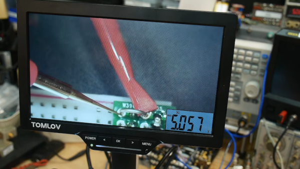
The microscope itself is one of those unremarkable ten-inch LCD screens with some lights and a USB camera. But it also has jacks for test probes, and the display shows up in the corner of the screen. It is a normal enough digital meter except for the fact that its display is on the screen.

If you had to document test results, this might be just the ticket. If you are probing tiny little SMD parts under the scope, you may find it useful, too, so you don’t have to look away from what you are working on when you want to take a measurement. Although for that, you could probably just have a normal display in the bezel, and it would be just as useful.

At about $180 USD, it’s not exactly an impulse buy. We wonder if we’ll someday see an oscilloscope microscope. That might be something. These cheap microscopes are often just webcams with additional optics. You can do the same thing with your phone. If you don’t need the microscope, but you like the idea, can we interest you in a heads-up meter?

Continue reading “Digital Microscope With An On-Screen Multimeter”

Dentist Tool Hardware Inspires Non-Slip Probe Tips

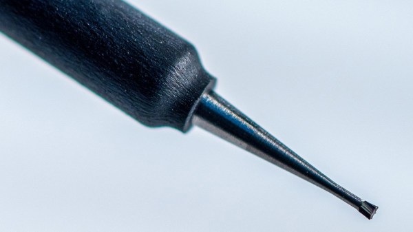
Cross-pollination between different industries can yield interesting innovations, and a few years ago [John Wiltrout] developed some non-slip meter probe adapters. He recently used our tips line to share some details that you won’t see elsewhere, letting us know how the idea came to be.

It started with [John] being frustrated by issues that will sound familiar: probes did not always want to stay in place, and had a tendency to skid around at the slightest provocation. This behavior gets only more frustrating as boards and components get smaller. John was also frustrated by the general inability to reliably probe through barriers like solder masking, oxidation, and conformal treatments on circuit boards. Continue reading “Dentist Tool Hardware Inspires Non-Slip Probe Tips”

Your Multimeter Might Be Lying To You

Multimeters are indispensable tools when working on electronics. It’s almost impossible to build any but the most basic of circuits without one to test and troubleshoot potential issues, and they make possible a large array of measurement capabilities that are not easily performed otherwise. But when things start getting a little more complex it’s important to know their limitations, specifically around what they will tell you about circuits designed for high frequency. [watersstanton] explains in this video while troubleshooting an antenna circuit for ham radio.

The issue that often confuses people new to radio or other high-frequency projects revolves around the continuity testing function found on most multimeters. While useful for testing wiring and making sure connections are solid, they typically only test using DC. When applying AC to the same circuits, inductors start to offer higher impedance and capacitors lower impedance, up to the point that they become open and short circuits respectively. The same happens to transformers, but can also most antennas which often look like short circuits to ground at DC but can offer just enough impedance at their designed frequency to efficiently resonate and send out radio waves.

This can give some confusing readings, such as when testing to make sure that a RF connector isn’t shorted out after soldering it to a coaxial cable for example. If an antenna is connected to the other side, it’s possible a meter will show a short at DC which might indicate a flaw in the soldering of the connector if the user isn’t mindful of this high-frequency impedance. We actually featured a unique antenna design recently that’s built entirely on a PCB that would show this DC short but behaves surprisingly well when sending out WiFi signals.

Continue reading “Your Multimeter Might Be Lying To You”

Peer-Reviewed Continuity Tester

One of the core features of the scientific community is the concept of “peer review” where any claims made by a scientist are open to be analyzed and reproduced by others in the community for independent verification. This leads to either rejection of ideas which can’t be reproduced, or strengthening of those ideas when they are. In this community we typically only feature the first step of this process, the original projects from various builders, but we don’t often see someone taking those instructions and “peer reviewing” someone’s build. This is one of those rare cases.

[oxullo] came across [Leo]’s original build for the ultimate continuity tester. This design is much more sensitive than the function which is built in to most multi-meters, and when building this tool specifically some other refinements can be built in as well. [oxullo] began by starting with the original designs, but made several small modifications. Most of these were changing to surface-mount parts, and switching some components for ones already available. Even then, there was still a mistake in the PCB which was eventually corrected. The case for this build is also 3D printed instead of being made out of metal, and with the original video to work from the rest fell into place easily.

[oxullo] is getting comparable results with this continuity tester, so we can officially say that this design is peer reviewed and tested to the highest of standards. If you’re in need of a more sensitive continuity sensor, or just don’t want to shell out for a Fluke meter when you don’t need the rest of its capabilities, this is the way to go. And don’t forget to check out our original write-up for this tester if you missed it the first time around.

Hacking A New Display Into A Fluke 8050A Multimeter

Old lab equipment was often built to last, and can give decades of service when treated properly. It’s often so loved that when one part fails, it’s considered well worth repairing rather than replacing with something newer. [Michael] did just that, putting in the work to give his Fluke 8050A multimeter a shiny new display.

The Fluke 8050A is a versatile device, capable of measuring voltage, current, and resistance in addition to decibels at various impedences and conductance, too. The original display doesn’t show some of the finer details so well, so [Michael] elected to improve on that when he installed a new 2.2″ graphical LCD to replace the basic 7-segment LCD that originally came with the hardware.

To achieve the install, the original LCD display module was removed from the chassis. A piggyback device that sits under the Fluke’s microcontroller was then used to break out signals for the new graphical LCD without requiring modification to the meter’s PCB itself. An Atmega32u4 microcontroller then takes in these signals, and then drives the graphical LCD accordingly.

It’s a great hack that makes the old multimeter easier to use, and the new white-on-green display is far kinder on the eyes, too. We’ve seen other multimeters get screen transplants before, too. Of course, if you’re new to the world of segmented LCDs and want to learn more about how they work, [Joey Castillo]’s talk from last year’s Remoticon will get you up to speed!

Detailed Big Screen Multimeter Review

It seems like large-screen cheap meters are really catching on. [TheHWcave] does a very detailed review of a KAIWEETS KM601, which is exactly the same as a few dozen other Chinese brands you can get from the usual sources. You can see the review in the video below.

If we learned nothing else from this video, we did learn that you can identify unmarked fuses with a scale. The fuses inside were not marked, so he wanted to know if they appeared to be the right values. We would have been tempted to just blow them under controlled conditions, but we get he didn’t want to destroy the stock fuses until after testing.

Continue reading “Detailed Big Screen Multimeter Review”