Turing Ring Is Compact

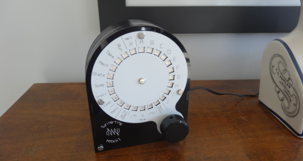
One of the problems with a classic Turing machine is the tape must be infinitely long. [Mark’s] Turing Ring still doesn’t have an infinite tape, but it does make it circular to save space. That along with a very clever and capable UI makes this one of the most usable Turing machines we’ve seen. You can see a demo in the video below.

The device uses an Arduino Nano, a Neopixel ring, an encoder, and a laser-cut enclosure that looks great. The minimal UI has several modes and the video below takes you through all of them.

Continue reading “Turing Ring Is Compact”

WS2812s On A 6502

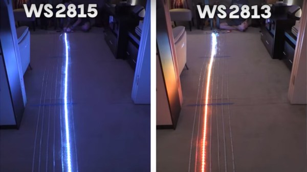
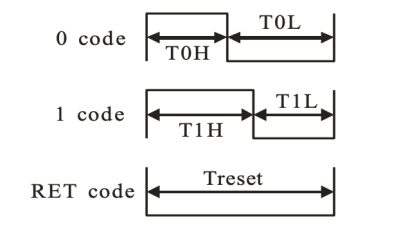
We can still remember when the WS2812 LED first came into our consciousness, way back in the mists of time. The timing diagrams in the datasheet-of-questionable-veracity made it sound quite tricky, with tight timing tolerances and essentially a high-speed two-bit PWM data protocol at 500 kHz. It was a challenge to bit-bang with an ATtiny85 back then, but there’s no way something as old and crusty as an Apple II would be up to snuff, right?

[Anders Nielsen] took up the challenge of getting the venerable 6502 processor to drive Neopixels and won! After all, if the chip is good enough for Bender and the Terminator T-800, it should be able to blink some colored LEDs, right? The secret sauce is shift registers!

Specifically, [Anders] abuses the 74LS165 parallel-in, serial-out shift register for his dirty work. Instead of bit-banging the WS2812’s “long high is a 1, short high is a 0” signal directly, the first few bits of the shift register are hard-wired to VCC and the last few to GND.

The bits in the middle determine if the pulse shifted out is long or short, and they’re set by the 6502, through a 6522 VIA chip, just like the Apple II would have. Clocking the data out of the shift register handles the timing-critical stuff. Very clever!

Video below the break.

Continue reading “WS2812s On A 6502”

Parts Shortage Forces Creativity For This Recursive Clock Of Clocks

We’ve been seeing a lot of metaclocks lately — a digital clock whose display is formed by the sweeping hands of an array of individual analog clocks. They can look fantastic, and we’ve certainly seen some great examples.

But in this time of supply pinches, it’s not always possible to gather the parts one needs for a full-scale build. Happily, that didn’t stop [Erich Styger] from executing this circular multi-metaclock with only thirteen of his custom dual-shaft stepper analog movements. Normally, his clocks use double that number of movements, which he arranges in a matrix so that the hands can be positioned to form virtual seven-segment displays. By arranging the movements in a circle, the light-pipe hands can mimic an analog clock face, or perform any of [Erich]’s signature “intermezzo” animations, each of which is graceful and engaging to watch. Check out a little of what this charmingly recursive clock has to offer in the video below.

[Erich] could easily have gotten stuck on the original design — he’s been at this metaclock game for a while, after all. The fact that the reduced part count forced him to get creative on the display is the best part of this build, at least to us.

Continue reading “Parts Shortage Forces Creativity For This Recursive Clock Of Clocks”

A Perfect Clock For Any Hacker’s Ohm

The vast majority of us are satisfied with a standard, base ten display for representing time. Fewer of us like to be a bit old-fashioned and use a dial with a couple of hands that indicate the time, modulo twelve. And an even smaller minority, with a true love for the esoteric, are a fan of binary readouts. Well, there’s a new time-telling game in town, and as far as we’re concerned it’s one of the best ones yet: resistor color codes.

The Ohm Clock is, as you may have guessed, a giant model of a resistor that uses its color bands to represent time.  Each of the four bands represents a digit in the standard HH:MM representation of time, and for anybody well-versed in resistor codes this is sure to be a breeze to read. The clock itself was designed by [John Bradnam]. It’s body is 3D printed, with RGB LEDs to brightly illuminate each segment. The whole thing is controlled by an old favorite – an ATtiny, supported by a Real Time Clock (RTC) chip for accurate timekeeping.

You can set the time in the traditional fashion using buttons, or — and here’s the brilliant part — you can use a resistor. Yup, that’s right. Connecting a 220 Ohm resistor across two terminals on the clock will set the time to 2:20. Genius.

When you come across an art as old as timekeeping, it’s easy to assume that everything’s already been done. We have sundials, hourglasses, analog clocks, digital watches, those cool clocks that use words instead of numbers, the list goes on. That’s why it’s so exciting to see a new (and fun!) idea like this one emerge.

Jigsaw Puzzle Lights Up With Each Piece

Putting the last piece of a project together and finally finishing it up is a satisfying feeling. When the last piece of a puzzle like that is a literal puzzle, though, it’s even better. [Nadieh] has been working on this jigsaw puzzle that displays a fireworks-like effect whenever a piece is placed correctly, using a lot of familiar electronics and some unique, well-polished design.

The puzzle is a hexagonal shape and based on a hexagonally symmetric spirograph, with the puzzle board placed into an enclosure which houses all of the electronics. Each puzzle piece has a piece of copper embedded in a unique location so when it is placed on the board, the device can tell if it was placed properly or not. If it was, an array of color LEDs mounted beneath a translucent diffuser creates a lighting effect that branches across the entire board like an explosion. The large number of pieces requires a multiplexer for the microcontroller, an ATtiny3216.

This project came out of a FabAcademy, so the documentation is incredibly thorough. In fact, everything on this project is open sourced and available on the project page from the code to the files required for cutting out the puzzle pieces and the enclosure. It’s an impressive build with a polish we would expect from a commercial product, and reminds us of an electrified jigsaw puzzle we saw in a previous build.

Thanks to [henk] for the tip!

LED Matrix Hack Chat

Join us on Wednesday, June 9 at noon Pacific for the LED Matrix Hack Chat with Garrett Mace!

It’s pretty amazing how quickly light-emitting diodes went from physics lab curiosity to a mainstream commodity product made in the millions, if not billions. Everything about LEDs has gotten better, smaller, and cheaper over the years, going from an “any color you want as long as it’s red” phase to all the colors of the rainbow and beyond in a relatively short time. LEDs have worked their way into applications that just didn’t seem likely not that long ago, like architectural lighting, automotive applications, and even immense displays covering billboards, buildings, and sporting venues with multicolor, high-resolution displays.

It’s that latter application that seems to have provided a boon to electronics hobbyists, in the form of cheap and plentiful LED matrix modules. These are easily sourced at the usual places, and with their tightly packed pinpoints that can show any color at any intensity, they have a ton of fun and useful applications for the hacker. But how exactly do you put them to use? Usually the electronics end is pretty straightforward, but some of the math involved in figuring out how to address all these LEDs can be a little mind-bending.

To help us sort all this out, Garrett Mace will drop by the Hack Chat. You’ve probably seen Garrett’s cool LED matrix shades, which have gone through a ton of revisions and are a much-copied fashion accessory among the cool hackers. They look simple, but there are tricks to making them work right, and Garrett will share his secrets. Come with your questions on putting LED matrix modules to work, especially those odd-size modules and strange arrangements that defy simple Cartesian coordinates.

join-hack-chatOur Hack Chats are live community events in the Hackaday.io Hack Chat group messaging. This week we’ll be sitting down on Wednesday, June 9 at 12:00 PM Pacific time. If time zones have you tied up, we have a handy time zone converter.

Click that speech bubble to the right, and you’ll be taken directly to the Hack Chat group on Hackaday.io. You don’t have to wait until Wednesday; join whenever you want and you can see what the community is talking about.

Triangle Tiles Form Blinky Networks Using Clever Interconnects

We love to see LEDs combined in all shapes and sizes, so we were especially ticked when we caught a glimpse of [Debra Ansell]’s (also known as [GeekMomProjects]) interlocking triangular TriangleLightPanel system glowing on our screen. This unusually shaped array seemed to be self supporting and brightly glowing, so we had to know more.

The TriangleLightPanel is a single, triangular, light panel (refreshing when everything is in the name, isn’t it?).  Each panel consists of a single white PCBA holding three side-firing SK6812 LEDs aimed inward, covered by transparent acrylic. When the LEDs are doing their thing, the three-position arrangement and reflective PCB surface does diffuses the light sufficiently to illuminate each pane — if not perfectly evenly — very effectively. Given the simple construction it’s difficult to imagine how they could be significantly improved.

The real trick is the mechanical arrangement. Instead of being connected with classic Dupont jumper wires and 0.1″ headers or some sort of edge connector, [Debra] used spring contacts. But if you’re confused by the lack of edge-plated fingers think again; the connectors are simple plated strips on the back. There is a second PCBA which effectively acts as wires and a surface to mount the spring contacts on, which is bolted onto the back of the connected leaves to bridge between each node. The tiles need to be mechanically connected in any case, so it’s a brilliantly simple way to integrate the electrical connection with the necessary mechanical one.

All the requisite source files are available on the project’s GitHub page and the original Tweets announcing the project are here for reference. We can’t wait to see what this would look like with another 30 or 40 nodes! Enterprising hackers are already building their own setup; see [arturo182]’s 24 tile array glowing after the break.

Continue reading “Triangle Tiles Form Blinky Networks Using Clever Interconnects”