Industrial Robot Gets Open-Source Upgrade

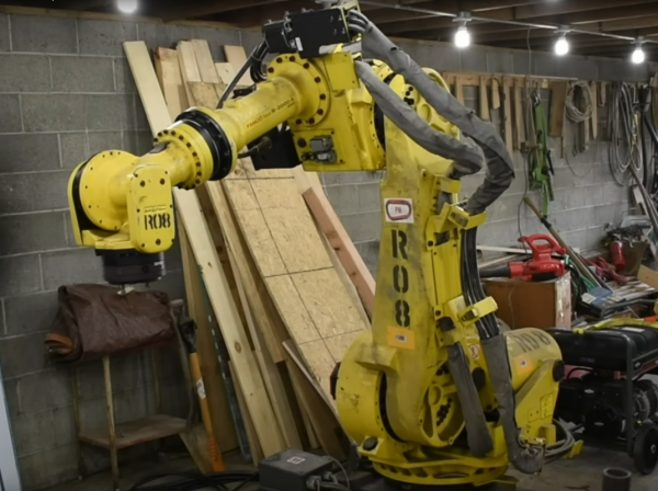
Industrial robots are shockingly expensive when new, typically only affordable for those running factories of some sort. Once they’ve gone through their life cycle building widgets, they can be purchased for little more than scrap value, which is essentially free compared to their original sticker price. [Excessive Overkill] explains all of this in a video where he purchased one at this stage to try to revive, but it also shows us how to get some more life out of these robots if you can spend some time hunting for spare parts, installing open-source firmware, and also have the space for a robot that weighs well over a thousand kilograms.

This specific robot is a Fanuc R2000ia with six degrees of freedom and a reach of over two meters. Originally the plan was to patch together a system that could send modern gcode to the Fanuc controller, but this was eventually scrapped when [Excessive Overkill] realized the controller that shipped with this robot was for an entirely different machine and would never work. Attempts to find upgraded firmware were frustrated, and after a few other false starts a solution was found to get the robot working again using LinuxCNC and Mesa FPGA cards, which have built-in support for Fanuc devices like this.

More after the break…

Continue reading “Industrial Robot Gets Open-Source Upgrade”

Carbon Fiber And Kevlar Make This Linear Actuator Fast And Strong

When it comes to the “build versus buy” question, “buy” almost always wins. The amount of time you have to put into building something is rarely justified, especially with a world of options available at the click of a mouse.

That’s not always the case, of course. These custom-made linear actuators are a perfect example of when building your own wins. For a planned ball-juggling robot, [Harrison Low] found himself in need of linear actuators with long throw distance, high speed, and stiff construction. Nothing commercially available checked all the boxes, so he set out to design his own.

A few design iterations later, [Harrison] arrived at the actuators you see in the video below. Built mainly from carbon fiber tubing and 3D-printed parts, the actuators have about 30 centimeters of throw, and thanks to their cable-drive design, they’re pretty fast — much faster than his earlier lead screw designs. The stiffness of the actuator comes by way of six bearings to guide the arm, arranged in two tiers of three, each offset by 60 degrees. Along with some clever eccentric spacers to fine-tune positioning, this design provides six points of contact that really lock the tube into place.

The cable drive system [Harrison] used is pretty neat too. A Kevlar kite string is attached to each end of the central tube and then through PTFE tubes to a pulley on an ODrive BLDC, which extends and retracts the actuator. It’s a clever design in that it keeps the weight of the motor away from the actuator, but it does have its problems, as [Harrison] admits. Still, the actuator works great, and it looks pretty cool while doing it. CAD and code are available if you want to roll your own.

These actuators are cool enough, but the real treat here will be the ball juggler [Harrison] is building. We’ve seen a few of those before, but this one looks like it’s going to be mighty impressive.

Continue reading “Carbon Fiber And Kevlar Make This Linear Actuator Fast And Strong”

Spinning ESP32 Display Puts The Customer First

Most of the projects we feature on Hackaday are built for personal use; designed to meet the needs of the person creating them. If it works for somebody else, then all the better. But occasionally we may find ourselves designing hardware for a paying customer, and as this video from [Proto G] shows, that sometimes means taking the long way around.

The initial task he was given seemed simple enough: build a display that could spin four license plates around, and make it so the speed could be adjusted. So [Proto G] knocked a frame out of some sheet metal, and used an ESP32 to drive two RC-style electronic speed controllers (ESCs) connected to a couple of “pancake” brushless gimbal motors. Since there was no need to accurately position the license plates, it was just a matter of writing some code that would spin the motors in an aesthetically pleasing way.

Unfortunately, the customer then altered the deal. Now they wanted a stand that could stop on each license plate and linger for a bit before moving to the next one. Unfortunately, that meant the ESCs weren’t up to the task. They got dumped in favor of an ODrive motor controller, and encoders were added to the shafts so the ESP32 could keep track of the display’s position. [Proto G] says he still had to work out some kinks, such as how to keep the two motors synchronized and reduce backlash when the spinner stopped on a particular plate, but in the end we think the results look fantastic. Now if only we had some license plates we needed rotisseried…

If [Proto G] knew he needed precise positioning control from the start, he would have approached the project differently and saved himself a lot of time. But such is life when you’re working on contract.

Continue reading “Spinning ESP32 Display Puts The Customer First”

Behold The Crimson Axlef*cker (Do Not Insert Finger)

Are your aluminum extrusions too straight? The Crimson Axlef*cker can help you out. It’s a remarkable 3D printed, 4-stage, 125:1 reduction gearbox driven by a brushless motor. Designer [jlittle988] decided to test an early prototype to destruction and while he was expecting something to break, he didn’t expect it to twist the 2020 aluminum extrusion shaft before it did. We suppose the name kind of stuck after that.

Internals of the first prototype, shaft of BLDC motor just visible at top. Twisted 2020 extrusion output shaft at bottom right.

[jlittle988] has been documenting the build progress on reddit, and recently posted a fascinating video (embedded below) of the revised gearbox twisting the output shaft even further. He’s a bit coy about the big picture, saying only that the unit is part of a larger project. In fact, despite the showy tests, his goal is not to simply obtain maximum torque. We can only speculate on what his bigger project is, but in the meantime, seeing the gearbox results is some good clean fun. He first announced the gearbox test results here, and swiftly followed it up with some revisions, then the aforementioned video. There’s also an image gallery of the internals, so check that out.

The Crimson Axlef*cker is driven by an ODrive brushless dual-shaft motor and an ODrive controller as well; that’s the same ODrive whose open source motor controller design impressed us so much in the past.

Between projects like this one and other gearboxes like this cycloidal drive, it’s clear that custom gearbox design is yet another door that 3D printing has thrown wide open, allowing hobbyists to push developments that wouldn’t have been feasible even just a few years earlier.

Continue reading “Behold The Crimson Axlef*cker (Do Not Insert Finger)”

Here’s Why Hoverboard Motors Might Belong In Robots

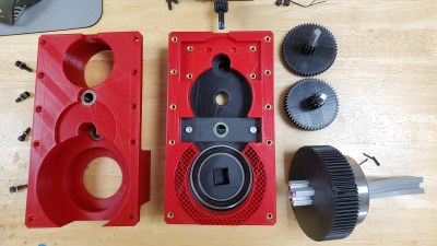
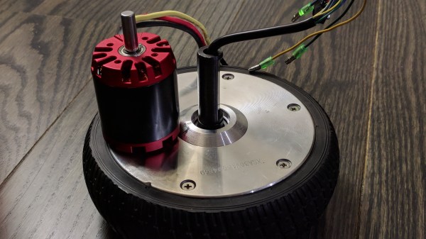
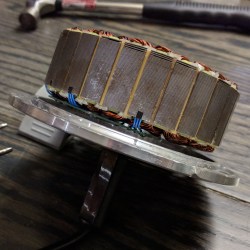
[madcowswe] starts by pointing out that the entire premise of ODrive (an open-source brushless motor driver board) is to make use of inexpensive brushless motors in industrial-type applications. This usually means using hobby electric aircraft motors, but robotic applications sometimes need more torque than those motors can provide. Adding a gearbox is one option, but there is another: so-called “hoverboard” motors are common and offer a frankly outstanding torque-to-price ratio.

A teardown showed that the necessary mechanical and electrical interfacing look to be worth a try, so prototyping has begun. These motors are really designed for spinning a tire on the ground instead of driving other loads, but [madcowswe] believes that by adding an encoder and the right fixtures, these motors could form the basis of an excellent robot arm. The ODrive project was a contender for the 2016 Hackaday Prize and we can’t wait to see where this ends up.