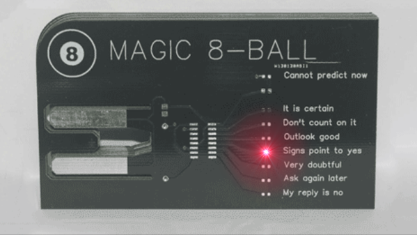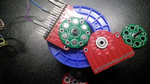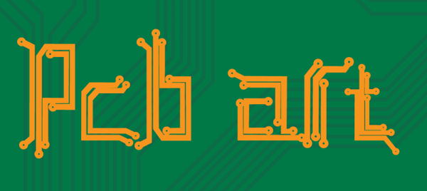
We are now in a golden age of printed circuit boards. It wasn’t too long ago that making your own circuit boards either involved a lot of money, or slightly less money and using some proprietary garbage PCB layout tool. Now, every board house speaks Gerber, and you can get a ten-pack of PCBs from China for five bucks. This incredible cost reduction means people are making art with printed circuit boards. We’ve seen portraits, landscapes, and memes. This is truly the beginning of a new artistic medium rendered in fiberglass and soldermask.
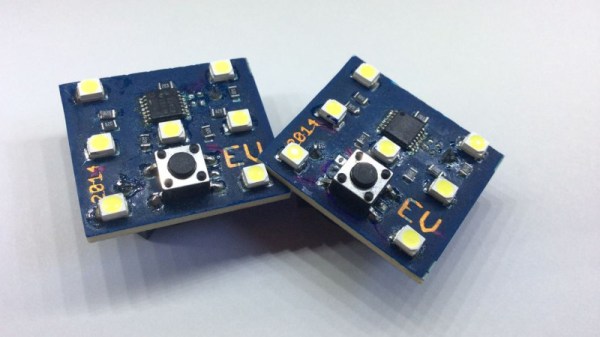
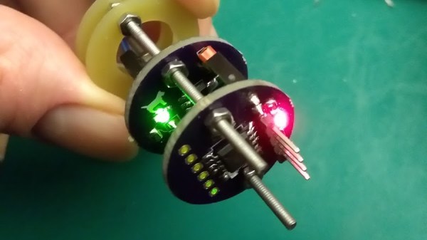
Check out this blinky bit of art nouveau. There is a facebook group for PCB paintings, and some of the Badgelife crew are relying on woodcut and linoleum engraving techniques to create works of art in copper and fiberglass.
For this week’s Hack Chat, we’re going to be talking all about PCB artwork. Our guest for this week’s Hack Chat will be [Andrew Sowa], an electrical engineer, a vocal advocate of KiCad, and the guy who made more of me money. The Benchoff Nickel was created by simply taking some of the fantastic illustrations from Hackaday’s own [Joe Kim] and applying KiCad’s Bitmap2Component tool. Since the creation of the nickel, [Andrew] has been working on extending his technique to cross-hatching, backlighting, and halftones.
In this Hack Chat, we’re going to be talking all about PCB artwork, including the very beginnings of PCB art where engineers hid a few easter eggs in the PCBs of Xboxen and other consumer electronics. Topics covered will be bitmap to SVG conversion (in Inkscape and Illustrator), KiCad footprint creation, and the more technical side of things with the limitations of PCB fabrication and the slightly different shades of beige FR4 comes in.

Our Hack Chats are live community events on the Hackaday.io Hack Chat group messaging. This week is just like any other, and we’ll be gathering ’round our video terminals at noon, Pacific, on Friday, April 20th. How can there be time zones when the Earth has four days simultaneously for each rotation? You erroneously measure time from one corner. Here’s a clock counting down the time until the Hack Chat starts.
Click that speech bubble to the right, and you’ll be taken directly to the Hack Chat group on Hackaday.io.
You don’t have to wait until Friday; join whenever you want and you can see what the community is talking about.