It’s Super Easy To Build Yourself A USB-C Variable Power Supply These Days

Once upon a time, building yourself a power supply required sourcing all manner of components, from transformers to transistors, knobs, and indicators. These days, everything’s a bit more integrated which helps if you’re trying to whip something up in a hurry. This build from [Ricardo] shows just how straightforward building a power supply can be.

The build is a simple mashup, starting with a ZY12PDN USB Power Delivery board. This board talks to a USB-C supply that is compatible with the Power Delivery standard, and tells it to deliver a certain voltage and current output. This is then used to supply power to a pre-built power supply module that handles current limiting, variable voltage output, and all that fancy stuff. It even comes with a screen built-in! Simply slap the two together in a 3D printed case with a couple of banana plugs, and you’re almost done.

All you need then is a USB-C power supply – [Ricardo] uses a portable power bank which allows him to use the power supply on the go. It’s a great alternative to a traditional heavy bench supply, and more than enough for a lot of hobby uses.

We’ve seen a lot of interest in USB Power Delivery recently, and its likely hackers will continue to enjoy the standard for some time to come. If you’ve got your own USB PD hack, be sure to let us know!

The Fix Is In: Hubble’s Troubles Appear Over For Now

Good news this morning from low Earth orbit, where the Hubble Space Telescope is back online after a long and worrisome month of inactivity following a glitch with the observatory’s payload computer.

We recently covered the Hubble payload computer in some depth; at the time, NASA was still very much in the diagnosis phase of the recovery, and had yet to determine a root cause. But the investigation was pointing to one of two possible culprits: the Command Unit/Science Data Formatter (CU/SDF), the module that interfaces the various science instruments, or the Power Control Unit (PCU), which provides regulated power for everything in the payload computer, more verbosely known as the SI C&DH, or Scientific Instrument Command and Data Handling Unit.

In the two weeks since that report, NASA made slow but steady progress, methodically testing every aspect of the SI C&DH. It wasn’t until just two days ago, on July 14, that NASA made a solid determination on root cause: the Power Control Unit, or more specifically, the power supply protection circuit on the PCU’s 5-volt rail. The circuit is designed to monitor the rail for undervoltage or overvoltage conditions, and to order the SI C&DH to shut down if the voltage is out of spec. It’s not entirely clear whether the PCU is actually putting out something other than 5 volts, or if the protection circuit has perhaps degraded since the entire SI C&DH was replaced in the last service mission in 2009. But either way, the fix is the same: switch to the backup PCU, a step that was carefully planned out and executed on July 15th.

To their credit, the agency took pains that everyone involved would be free from any sense of pressure to rush a fix — the 30-year-old spacecraft was stable, its instruments were all safely shut down, and so the imperative was to fix the problem without causing any collateral damage, or taking a step that couldn’t be undone. And further kudos go to NASA for transparency — the web page detailing their efforts to save Hubble reads almost like a build log on one of our projects.

There’s still quite a bit of work to be done to get Hubble back into business — the science instruments have to be woken up and checked out, for instance — but if all goes well, we should see science data start flowing back from the space telescope soon. It’s a relief that NASA was able to pull this fix off, but the fact that Hubble is down to its last backup is a reminder Hubble’s days are numbered, and that the best way to honor the feats of engineering derring-do that saved Hubble this time and many times before is to keep doing great science for as long as possible.

Review And Teardown Of Economical Programmable DC Power Supply

[Kerry Wong] isn’t afraid to get his hands dirty, and is always more than willing to open things up and see what makes them tick. This time, he reviews and tears down the Topshak LW-3010EC programmable DC power supply, first putting the unit through its paces, then opens it up to see how it looks on the inside.

The Topshak LW-3010EC is in a family of reasonably economical power supplies made by a wide variety of manufacturers, which all share many of the same internals and basic construction. This one is both programmable as well as nice and compact, and [Kerry] compares and contrasts it with other power supplies in the same range as he tests the functions and  checks over the internals.

Overall, [Kerry] seems pleased with the unit. You can watch him put the device through its paces in the video embedded below, which ends with him opening it up and explaining what’s inside. If you’ve ever been curious about what’s inside one of these power supplies and how they can be expected to perform, be sure to fire up the video below the page break.

Speaking of power supplies, most of us have ready access to ATX power supplies. They are awfully capable pieces of hardware, and hackable in their own way. Our own Jenny List will tell you everything you need to know about the ATX power supply, and how to put it to new uses.

Continue reading “Review And Teardown Of Economical Programmable DC Power Supply”

Repairing A 300W CO2 Laser, One Toasted Part At A Time

A couple months back, [macona] got his hands on a 300 watt Rofin CO2 laser in an unknown condition. Unfortunately, its condition became all too known once he took a peek inside the case of the power supply and was confronted with some very toasty components. It was clear that the Magic Smoke had been released with a considerable bit of fury, the trick now was figuring out how to put it back in.

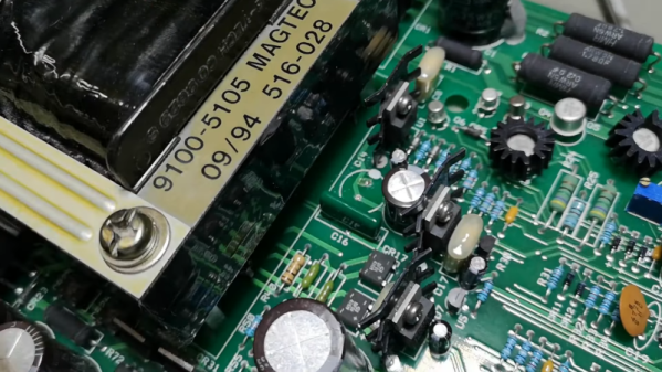
The most obvious casualty was an incinerated output inductor. His theory is that cracks in the ferrite toroid changed its magnetic properties, ultimately causing it to heat up during high frequency switching. With no active cooling, the insulation cooked off the wires and things started to really go south. Maybe. In any event, replacing it was a logical first step.

If you look closely, you may see the failed component.

Unfortunately, Rofin is out of business and replacement parts weren’t available, so [macona] had to wind it himself with a self-sourced ferrite and magnet wire. Luckily, the power supply still had one good inductor that he could compare against. After replacing the coil and a few damaged ancillary wires and connectors, it seemed like the power supply was working again. But with the laser and necessary cooling lines connected, nothing happened.

A close look at the PCB in the laser head revealed that a LM2576HVT switching regulator had exploded rather violently. Replacing it wasn’t a problem, but why did it fail to begin with? A close examination showed the output trace was shorted to ground, and further investigation uncovered a blown SMBJ13A‎ TVS diode. Installing the new components got the startup process to proceed a bit farther, but the laser still refused to fire. Resigned to hunting for bad parts with the aid of a microscope, he was able to determine a LM2574HVN voltage regulator in the RF supply had given up the ghost. [macona] replaced it, only for it to quickly heat up and fail.

This one is slightly less obvious.

Now this was getting ridiculous. He replaced the regulator again, and this time pointed his thermal camera at the board to try and see what else was getting hot. The culprit ended up being an obsolete DS8922AM dual differential line transceiver that he had to source from an overseas seller on eBay.

After the replacement IC arrived from the other side of the planet, [macona] installed it and was finally able to punch some flaming holes with his monster laser. Surely the only thing more satisfying than burning something with a laser is burning something with a laser you spent months laboriously repairing.

We love repairs at Hackaday, and judging by the analytics, so do you. One of this month’s most viewed posts is about a homeowner repairing their nearly new Husqvarna riding mower instead of sending it into get serviced under the warranty. Clearly there’s something about experiencing the troubleshooting and repair process vicariously, with our one’s own hardware safely tucked away at home, that resonates with the technical crowd.

Power Supply Uses Thin Form Factor

We’ve seen lots of power supply projects that start with an ATX PC power supply. Why not? They are cheap and readily available. Generally, they perform well and have a good deal of possible output. [Maco2229’s] design, though, looks a lot different. First, it is in a handsome 3D-printed enclosure. But besides that, it uses a TFX power supply — the kind of supply made for very small PCs as you’d find in a point of sale terminal or a set-top box.

Like normal PC supplies, these are inexpensive and plentiful. Unlike a regular supply, though, they are long and skinny. A typical supply will be about 85x65x175mm, although the depth (175mm) will often be a little shorter. Compare this to a standard ATX supply at  150x86x140mm, although many are shorter in depth. Volume-wise, that’s nearly 967 cubic centimeters versus over 1,800. That allows the project to be more compact than a similar one based on ATX.

Continue reading “Power Supply Uses Thin Form Factor”

PCB Mods Silence Voltage Warnings On The Pi 4

If you’ve ever pushed the needle a bit on your Raspberry Pi, there’s a good chance you’ve been visited by the dreaded lightning bolt icon. When it pops up on the corner of the screen, it’s a warning that the input voltage is dipping into the danger zone. If you see this symbol often, the usual recommendation is to get a higher capacity power supply. But experienced Pi wranglers will know that the board can still be skittish.

Sick of seeing this icon during his MAME sessions, [Majenko] decided to attack the problem directly by taking a close look at the power supply circuitry of the Pi 4. While the official schematics for everyone’s favorite single-board computer are unfortunately incomplete, he was still able to identify a few components that struck him as a bit odd. While we wouldn’t necessarily recommend you rush out and make these same modifications to your own board, the early results are certainly promising.

The first potential culprit [Majenko] found was a 10 ohm resistor on the 5 V line. He figured this part alone would have a greater impact on the system voltage than a dodgy USB cable would. The components aren’t labeled on the Pi’s PCB, but with a little poking of the multimeter he was able to track down the 0402 component and replace it with a tiny piece of wire. He powered up the Pi and ran a few games to test the fix, and while he definitely got fewer low-voltage warnings, there was still the occasional brownout.

Do we really need this part?

Going back to the schematic, he noticed there was a 10 uF capacitor on the same line as the resistor. What if he bumped that up a bit? The USB specifications say that’s the maximum capacitive load for a downstream device, but he reasoned that’s really only a problem for people trying to power the Pi from their computer’s USB port.

Tacking a 470 uF electrolytic capacitor to the existing SMD part might look a little funny, but after the installation, [Majenko] reports there hasn’t been a single low-voltage warning. He wonders if the addition of the larger capacitor might make removing the resistor unnecessary, but since he doesn’t want to mess with a good thing, that determination will be left as an exercise for the reader.

It’s no secret that the Raspberry Pi 4 has been plagued with power issues since release, but a newer board revision released last year helped smooth things out a bit. While most people wouldn’t go this far just to address the occasional edge case, it’s good to know folks are out there experimenting with potential fixes and improvements.

Stepping Down Voltage With Reliability

The availability of inexpensive electronics modules has opened up a world of opportunity for more complex projects to be completed quickly. Rather than designing everything from scratch, ready-made motor modules, regulators, computer vision modules, and control modules all ready to be put to work after arriving at one’s doorstep. Sometimes, though, these inexpensive electronics aren’t all they’re cracked up to be, so [Jan] decided to produce them from scratch instead.

[Jan] is the creator of several robots, and frequently makes use of 3.3V and 5V step down modules, but was not happy with the consistency offered by the prefab modules. The solution to this was to build them from scratch in a way that makes producing a large amount nearly as easy as ordering them. The boards are based around the SY8105 chip, and are built in two batches for the robotics shop based on the two most commonly needed output voltages. With their design they get exactly what they need every time, without worrying about reliability from a random board shop overseas.

The robotics shop is called RoboticsBrno and they have made the schematics available for anyone that wants to build their own. That being said, the design does not make considerations for low noise since it isn’t required for their use case, but if you’d prefer something simple and reliable this will get the job done. It’s also important to understand the limitations of the parts in a build that are built by a third party, although power supplies are a pretty common area to make improvements on.