Shed Pounds And Inches While Binge Watching Netflix

Feel like breaking out of your streaming-induced vegetative state but can’t seem to break the binge-watching cycle? Maybe you’re a candidate for this exercise bike that controls how much Netflix you watch.

The concept behind [Roboro]’s anti-couch potato build is simple — just keep pedaling and you get to keep watching. The details are pretty simple too and start with an Arduino monitoring the signal coming from a jack thoughtfully provided by the manufacturer of his exercise bike. The frequency of the square wave is translated into a speed which a Python script on a PC reads over USB. Once a Netflix stream is started, dropping below the user-defined speed pauses the movie. The video below shows it doing its thing.

Improvements readily spring to mind, like adding a speed buffer so that pedaling faster lets you bank some streaming time and earn a rest. Maybe it could somehow integrate with these Netflix-enabled socks, or even with the Netflix and Chill button. But those sort of defeat the purpose a bit.

Continue reading “Shed Pounds And Inches While Binge Watching Netflix”

Taking The Pulse (Width Modulation) Of An FPGA

I like to think that there are four different ways people use FPGAs:

  1. Use the FPGA as a CPU which allows you to add predefined I/O blocks
  2. Build custom peripherals for an external CPU from predefined I/O blocks
  3. Build custom logic circuitry from scratch
  4. Projects that don’t need an FPGA, but help you learn

I’d bet the majority of FPGA use falls into categories one and two. Some FPGAs even have CPUs already built-in. Even without an onboard CPU, you can usually put a CPU “core” (think reusable library) into the chip. Either way, you can always add other cores to create UARTs, USB, Ethernet, PWM, or whatever other I/O you happen to need. You either connect them to a CPU on the chip, or an external one. With today’s tools, you often pick what you want from a list and then your entire project becomes a software development effort.

Continue reading “Taking The Pulse (Width Modulation) Of An FPGA”

Attiny PWM Generator And Servo Tester

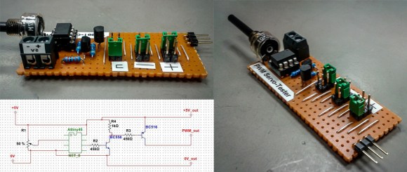
PWM-Servo-Tester

Having the right tool for the job makes all the difference, especially for the types of projects we feature here at Hackaday. [Jana Marie] must agree with this sentiment, one of her latest projects involves building a tool to generate a PWM signal and test servos using an Attiny25/45/85.

Tools come in all kinds of different shapes and sizes. Even if it might not be as widely used as [Jana’s] earlier work that combines an oscilloscope and signal generator, having a tool that you can rely upon to test servos and generate a PWM can be very useful. This well written Instructable provides all the details you need to build your own, including the schematic and the necessary code (available on GitHub). The final PWM generator looks great. For simple projects, sometimes a protoboard is all you need. It would be very cool to see a custom PCB made for this project in the future.

What tools have you build recently? Indeed, there is a tool for every problem. Think outside the (tool) box and let us know what you have made!

Simple 10 Watt LED Driver Is Hot Stuff

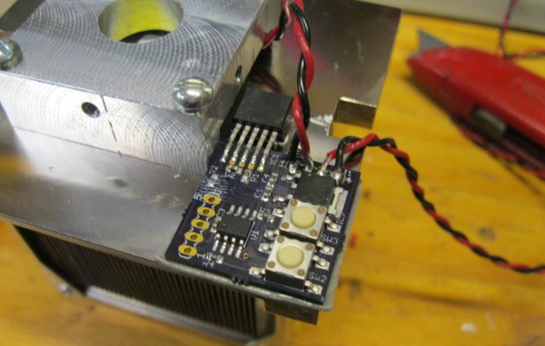
[Peter] needed to drive a high power LED for his microscope. Rather than pick up a commercial LED driver, he built a simple constant current LED driver and fan control. We’ve featured [Peter’s] pumpkin candle LED work here on Hackaday in the past. Today he’s moving on to higher power LEDs. A 10 watt LED would be a good replacement light source for an old halogen/fiber optic ring light setup. [Peter] started with his old standby – an 8 pin Microchip PIC. In this case, a PIC12F1501. A PIC alone won’t handle a 10 watt LED, so he utilized a CAT4101 constant current LED driver from ON Semi. The PIC performs three tasks in this circuit. It handles user input from two buttons, generates a PWM signal to the LED driver, and generates a PWM signal for a cooling fan.

Control is simple: Press both buttons and the LED comes on full bright. Press the “up” button, and the LED can be stepped up from 10% to 100% in 10 steps.  The “down” button drops the LED power back down. [Peter] even had a spare pin. He’s currently using it as an LED on/off confirmation, though we’d probably use it with a 1wire temperature sensor as a backup to thermal protection built into the CAT4101. It may be overkill, but we’d also move the buttons away from that 7805 linear regulator. Being that this circuit will be used with a microscope, it may eventually be operated by touch alone. It would be a bit surprising to try to press a button and end up with a burnt fingertip!

Continue reading “Simple 10 Watt LED Driver Is Hot Stuff”

Octoscroller Takes The Hexascroller To The Next Level

octosc2

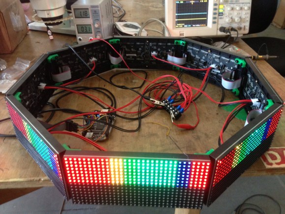
The folks at NYCResistor have a new toy in the Octoscroller. For a couple of years now the NYCResistor crew has used the HexaScroller as a clock and general alert system. Now that RGB LED panels are cheaply available, the group decided to upgrade both the number of sides and the number of colors.

Octoscroller uses eight 16×32 RGB LED panels. These panels are relatively easy to interface to, but require constant refresh even to display a static image. This makes them both memory and CPU intensive for smaller microcontrollers. Brightness control via PWM only increases the difficulty.

On the plus side, the panels are structurally strong. This allows the Octoscroller to avoid the plywood ring which made up the frame of the Hexascroller. 3D printed brackets and hardware were all that was needed to complete the Octoscroller frame.

The brain of the this beast is a BeagleBone Black running LEDscape along with some custom software. Imagery comes from the Disorient Pyramid.

If you’re in the New York area, NYCResistor plans to offer classes on building your own Octoscroller.  You can also see the Octoscroller in person at MakerFaire NYC this weekend.

Pulse Width Modulation With Microcontrollers

Those following the ProtoStack tutorials will be happy to hear that there is a new installment which explains Pulse Width Modulation. If you’ve never heard of PWM before, it’s a method of generating a signal that is logic 1 for a portion of the time and logic 0 for the remainder of the time. It is the most commonly used method for dimming an LED, and that’s [Daniel’s] example in this tutorial. But you’ll also find it used in many other applications such as servo motor control and piezo speaker control.

[Daniel] starts off with a brief explanation of duty cycle, then moves on to some examples of hardware and software PWM. Many of the AVR microcontrollers have a hardware PWM feature that allows you to configure a pin that toggles based on a target timer value. This is demonstrated using an ATmega168, but a method of using interrupts and your own code is also covered in case you don’t have a hardware PWM pin available.