How Airplanes Mostly Stopped Flying Into Terrain And Other Safety Improvements

We have all heard the statistics on how safe air travel is, with more people dying and getting injured on their way to and from the airport than while traveling by airplane. Things weren’t always this way, of course. Throughout the early days of commercial air travel and well into the 1980s there were many crashes that served as harsh lessons on basic air safety. The most tragic ones are probably those with a human cause, whether it was due to improper maintenance or pilot error, as we generally assume that we have a human element in the chain of events explicitly to prevent tragedies like these.

Among the worst pilot errors we find the phenomenon of controlled flight into terrain (CFIT), which usually sees the pilot losing track of his bearings due to a variety of reasons before a usually high-speed and fatal crash. When it comes to keeping airplanes off the ground until they’re at their destination, here ground proximity warning systems (GPWS) and successors have added a layer of safety, along with stall warnings and other automatic warning signals provided by the avionics.

With the recent passing of C. Donald Bateman – who has been credited with designing the GPWS – it seems like a good time to appreciate the technology that makes flying into the relatively safe experience that it is today.

Continue reading “How Airplanes Mostly Stopped Flying Into Terrain And Other Safety Improvements”

Satellite Provides Detailed Data On Antarctic Ice

Ever since the first satellites started imaging the Earth, scientists have been using the data gathered to learn more about our planet and improve the lives of its inhabitants. From weather forecasting to improving crop yields, satellites have been put to work in a wide array of tasks. The data they gather can go beyond imaging as well. A new Chinese satellite known as Fengyun-3E is using some novel approaches to monitor Antarctic sea ice in order to help scientists better understand the changing climate at the poles.

While it is equipped with a number of other sensors, one of the more intriguing is a piece of equipment called WindRad which uses radar to measure wind at various locations and altitudes based on how the radar waves bounce off of the atmosphere at various places.  Scientists have also been able to use this sensor to monitor sea ice, and can use the data gathered to distinguish new sea ice from ice which is many years old, allowing them to better understand ice formation and loss at the poles. It’s also the first weather satellite to be placed in an early morning orbit, allowing it to use the long shadows cast by the sun on objects on Earth’s surface to gather more information than a satellite in other orbits might be able to.

With plenty of other imaging sensors on board and a polar orbit, it has other missions beyond monitoring sea ice. But the data that it gathers around Antarctica should give scientists more information to improve climate models and understand the behavior of sea ice at a deeper level. Weather data from satellites like these isn’t always confined to academia, though. Plenty of weather satellites broadcast their maps and data unencrypted on radio bands that anyone can access.

Street Photography, With RADAR!

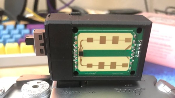
As the art of film photography has gained once more in popularity, some of the accessories from a previous age have been reinvented, as is the case with [tdsepsilon]’s radar rangefinder. Photographers who specialized in up-close-and-personal street photography in the mid-20th century faced the problem of how to focus their cameras. The first single-lens reflex cameras (SLRs) were rare and expensive beasts, so for most this meant a mechanical rangefinder either clipped to the accessory shoe, or if you were lucky, built into the camera.

The modern equivalent uses an inexpensive 24 GHz radar module coupled to an ESP32 board with an OLED display, and fits in a rather neat 3D printed enclosure that sits again in the accessory shoe. It has a 3 meter range perfect for the street photographer, and the distance can easily be read out  and dialed in on the lens barrel.

Whenever the revival of film photography is discussed, it’s inevitable that someone will ask why, and point to the futility of using silver halides in a digital age. It’s projects like this one which answer that question, with second-hand SLRs being cheap and plentiful you might ask why use a manual rangefinder over one of them, but the answer lies in the fun of using one to get the perfect shot. Try it, you’ll enjoy it!

Some of us have been known to dabble in film photography, too.

Thanks [Joyce] for the tip.

‘Radar’ Glasses Grant Vision-free Distance Sensing

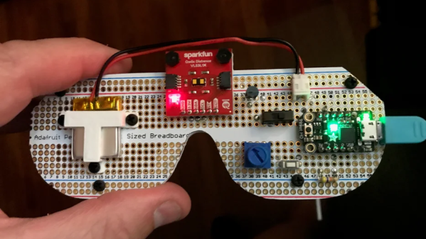
[tpsully]’s Radar Glasses are designed as a way of sensing the world without the benefits of normal vision. They consist of a distance sensor on the front and a vibration motor mounted to the bridge for haptic feedback. The little motor vibrates in proportion to the sensor’s readings, providing hands-free and intuitive feedback to the wearer. Inspired in part by his own experiences with temporary blindness, [tpsully] prototyped the glasses from an accessibility perspective.

The sensor is a VL53L1X time-of-flight sensor, a LiDAR sensor that measures distances with the help of pulsed laser light. The glasses do not actually use RADAR (which is radio-based), but the operation is in a sense quite similar.

The VL53L1X has a maximum range of up to 4 meters (roughly 13 feet) in a relatively narrow field of view. A user therefore scans their surroundings by sweeping their head across a desired area, feeling the vibration intensity change in response, and allowing them to build up a sort of mental depth map of the immediate area. This physical scanning resembles RADAR antenna sweeps, and serves essentially the same purpose.

There are some other projects with similar ideas, such as the wrist-mounted digital white cane and the hip-mounted Walk-Bot which integrates multiple angles of sensing, but something about the glasses form factor seems attractively intuitive.

Thanks to [Daniel] for the tip, and remember that if you have something you’d like to let us know about, the tips line is where you can do that.

Dark Trace CRTs, Almost The E-Ink Of Their Time

When you’ve been a fact-sponge for electronics trivia for over four decades, it’s not often that an entire class of parts escapes your attention. But have you seen the Skiatron? It’s a CRT that looks like a normal mid-20th-century tube, until it’s switched on. Then its secret is revealed; instead of the glowing phosphor trace we’d expect, the paper-white screen displays a daylight-readable and persistent black trace. They’re invariably seen in videos of radar installations, with the 360 degree scans projected onto large table-top screens which show the action like a map. It’s like e-ink, but from the 1940s. What’s going on?

Two photos of the same crystalline rock, the top one is white, the bottom one is purple.
The tenebrescent mineral Hackmanite, before and after UV exposure. Leland Green…, CC BY-SA 2.0 and CC BY-SA 2.0.

The phosphor coating on a traditional CRT screen is replaced by a halide salt, and the property on which the display relies is called tenebrescence, changing colour under the influence of radiation. This seems most associated online with UV treatment of some minerals and gemstones to give them a prettier look, and its use a s a display technology is sadly forgotten.

A high-school physics understanding of the phenomenon is that energy from the UV light or the electron beam in the case of the tube, places some electrons in the crystal into higher energy levels, at which they absorb some visible light wavelengths. This is reversible through heat, in some substances requiring the application of heat while in others the heat of room temperature being enough. Of course here at Hackaday we’re hands-on people, so into the EPROM eraser went a small amount of table salt in a makeshift dish made of paper, but sadly not to be rewarded by a colour change.

On a real dark-trace CRT the dark trace would be illuminated from behind by a ring light round the glass neck of the tube. An interesting aside is that, unlike phosphor CRTs, they were more suitable for vertical mounting. It seems that small amounts of phosphor could detach themselves from a vertically mounted screen and drop into the electron gun, something that wasn’t a problem for tenebrescent coatings.

This display tech has shuffled off into the graveyard of obsolescence, we’re guessing because CRT technology became a lot better over the 1950s, and radar technologies moved towards a computerised future in which the persistence of the display wasn’t the only thing keeping the information on the screen. It seems at first sight to be a surprise that tenebrescent coatings have never resurfaced in other displays for their persistence, but perhaps there was always a better alternative whether it was ultra-low-power LCDs or more recently e-ink style devices.

For more bleeding-edge 1950s radar displays, we’ve previously brought you Volscan, a radar with an early form of GUI, which no doubt was one of those which consigned dark-trace CRTs to history.

The Device That Won WW2: A History Of The Cavity Magnetron

[Curious Droid] is back with a history lesson on one of the most important inventions of the 20th century: The cavity magnetron. Forged in the fighting of World War II, the cavity magnetron was the heart of radar signals used to identify attacking German forces.

The magnetron itself was truly an international effort, with scientists from many countries providing scientific advances. The real breakthrough came with the work of  [John Randall] and [Harry Boot], who produced the first working prototype of a cavity magnetron. The device was different than the patented klystron, or even earlier magnetron designs. The cavity magnetron uses physical cavities and a magnetic field to create microwave energy.  The frequency is determined by the size and shape of the cavities.

While the cavity magnetron had been proven to work, England was strapped by the war effort and did not have the resources to continue the work. [Henry Tizzard] brought the last prototype to the USA where it was described as “the most valuable cargo ever brought to our shores”. The cavity magnetron went on to be used throughout the war in RADAR systems both air and sea.

Today, many military RADAR systems use klystrons or traveling wave tube amplifiers due to requirements for accurate frequency pulses.  But the cavity magnetron still can be found in general and commercial aviation RADAR systems, as well as the microwave ovens we all know and love.

Check the video out after the break.

Continue reading “The Device That Won WW2: A History Of The Cavity Magnetron”

Doppler Speed Sensor Puts FFT And AGC To Work

Some people hate to revisit projects that are done and dusted. We get that; it’s a little like reading a book you’ve already read when there are so many others to choose from. But rereading a book sometimes reveals subtle nuances you missed the first time around, and revisiting projects can be much the same, as with this new and improved Doppler radar speed sensor.

We seem to have been remiss in writing up [Limpkin]’s last go-around with the CDM324 microwave module, a 24-GHz transceiver that you can pick up on the cheap from the usual sources, but we’ve featured this handy little module in plenty of other projects. [Limpkin]’s current project uses the same module to create a Doppler speed sensor, but with a little more sophistication all around. Whereas the original used a simple comparator to output a square wave that’s proportional to the Doppler shift and displayed the speed on a simple terminal session, version two takes a different tack.

First, [Limpkin] opted to implement the whole sensor in hardware. The front end is quite different — an op-amp with 84 dB of gain followed by an automatic gain control (AGC) stage built from a MAX9814 microphone preamp. Extraction of the speed from the module output is left to an STM32F301 running an FFT algorithm on the signal coming out of the analog circuit, which essentially picks out the biggest peak in the spectrum and calculates the Doppler shift from that, displaying the results on an LCD display.

Of course, as a [Limpkin] project, there’s a lot more to it than just that. The write-up is very detailed, going down a few enjoyable rabbit holes like characterizing the amplification chain and diving into the details of Johnson-Nyquist noise to chase down stray oscillations. There’s some great stuff here, and it’s well worth a deep read; there’s also the video below that lets you see (and hear) what’s going on.

Continue reading “Doppler Speed Sensor Puts FFT And AGC To Work”