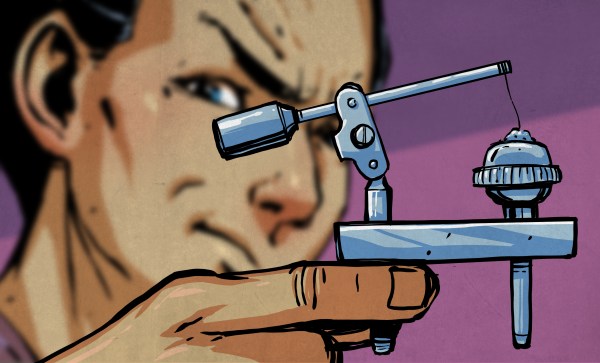
We’ve all been there – hiking in the woods with a dead phone battery. No GPS, no way to Tweet that selfie from some hill with a great vista. It’s a disaster! But not if you have access to a little trailside junk and have the ingenuity to build this field-expedient water wheel generator to recharge your phone.
OK, it’s a stretch to imagine finding all the things needed for [Thomas Kim]’s hack. We’re only guessing at the BOM – the video below has little commentary, so what you see is what you get – but it looks like a garbage can at the trailhead might at least yield the materials needed to build the turbine. Water bottle bottoms and a couple of plastic picnic plates form the Pelton-like impeller, the frame looks like an old drying rack, and the axle appears to be a campfire skewer. But you might have a hard time finding the electrical side of the build, which consists of a stepper motor, a rectifier, and an electrolytic cap. Then again, you could get lucky and find a cast-off printer by the side of the road. No matter how he got the materials, it’s pretty cool to see an iPhone recharging next to a babbling brook in the woods.
Looking for a little more oomph from your trash-heap hydroelectric turbine? Maybe you need to look at this washing machine power plant build.
The history of the diode is a fun one as it’s rife with accidental discoveries, sometimes having to wait decades for a use for what was found. Two examples of that are our first two topics: thermionic emission and semiconductor diodes. So let’s dive in.
Vacuum Tubes/Thermionic Diodes
Our first accidental discovery was of thermionic emission, which many years later lead to the vacuum tube. Thermionic emission is basically heating a metal, or a coated metal, causing the emission of electrons from its surface.
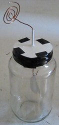
Electroscope
In 1873 Frederick Guthrie had charged his electroscope positively and then brought a piece of white-hot metal near the electroscope’s terminal. The white-hot metal emitted electrons to the terminal, which of course neutralized the electroscope’s positive charge, causing the leafs to come together. A negatively charged electroscope can’t be discharged this way though, since the hot metal emits electrons only, i.e. negative charge. Thus the direction of electron flow was one-way and the earliest diode was born.
Thomas Edison independently discovered this effect in 1880 when trying to work out why the carbon-filaments in his light bulbs were often burning out at their positive-connected ends. In exploring the problem, he created a special evacuated bulb wherein he had a piece of metal connected to the positive end of the circuit and held near the filament. He found that an invisible current flowed from the filament to the metal. For this reason, thermionic emission is sometimes referred to as the Edison effect.
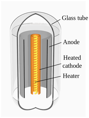
Thermionic diode. By Svjo [CC BY-SA 3.0], via Wikimedia CommonsBut it took until 1904 for the first practical use of the effect to appear. John Ambrose Fleming had actually consulted for the Edison Electric Light Company from 1881-1891 but was now working for the Marconi Wireless Telegraph Company. In 1901 the company demonstrated the first radio transmission across the Atlantic, the letter “S” in the form or three dots in Morse code. But there was so much difficulty in telling the received signal apart from the background noise, that the result was disputed (and still is). This made Fleming realize that a more sensitive detector than the coherer they’d been using was needed. And so in 1904 he tried an Edison effect bulb. It worked well, rectifying the high frequency oscillations and passing the signals on to a galvanometer. He filed for a patent and the Fleming valve, the two element vacuum tube or thermionic diode, came into being, heralding decades of technological developments in many subsequent types of vacuum tubes.
Vacuum tubes began to be replaced in power supplies in the 1940s by selenium diodes and in the 1960s by semiconductor diodes but are still used today in high power applications. There’s also been a resurgence in their use by audiophiles and recording studios. But that’s only the start of our history.
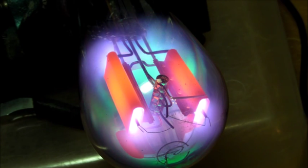
[Eric] has an Atwater Kent 55C AM radio from the early 1900’s. He’s been trying to restore the radio to proper working condition. His most recent pain has been with the rectifier tube. The tube is supposed to have a complete vacuum inside, but that’s not the case here. When the tube is powered up, it glows a beautiful violet color. It may look pretty, but that’s indicative that gas has leaked into the tube. It needed to be replaced.
[Eric] had a tube that would serve as a good replacement, but it’s plug didn’t fit the socket properly. He was going to have to use this old broken tube to make an adapter. Rather than just tearing the old tube apart, he decided to have some fun with it first. He hooked it up to a variac, an ammeter, and a volt meter. Then he slowly increased the voltage to see what would happen. The result was visually stunning.
The tube starts out with the same violet/blue glowing [Eric] experienced previously. As the voltage increases, it gets more and more intense. Eventually we start to see some green colors mixing in with the violets. [Eric’s] reaction to this unexpected result is priceless. As the tube gets increasingly hot, the anode starts glowing an orange-red color. Finally, the filament starts to crackle like a sparkler before the tube just gives up and completely fails.
After the light show, [Eric] moves on to replacing the tube. He begins by tapping on the old tube’s socket with the end of a screwdriver. After much tapping, the glass starts to come lose from the socket. After a bit of wiggling and twisting the tube finally came free from the socket. [Eric] luckily had an unused octal socket that fit perfectly inside of the old socket. All he needed to do to build his adapter was to connect the four pins from the old adapter to the proper pins on the octal socket. Piece of cake.
…Or so [Eric] thought. After testing some new tubes with a tube tester, he realized he had soldered all four pins incorrectly. On top of that, he had super glued the adapter together. He eventually got the two pieces apart. This time he removed all of the unused pins from the octal socket so he wouldn’t get it wrong. Another run on the tube tester confirmed that everything looked good. After plugging the tube into the radio, it worked just as expected
If you need fabrication rather than repair, we’ve got you covered there as well. Check out [Charles Alexanian’s] process for making new vacuum tubes in his garage. Now if you just have too darn many of them around, you can always decorate your pad with ’em.
When his 6 years old induction cooker recently broke, [Johannes] decided to open it in an attempt to give it another life. Not only did he succeed, but he also added Bluetooth connectivity to the cooker. The repair part was actually pretty straight forward, as in most cases the IGBTs and rectifiers are the first components to break due to stress imposed on them. Following advice from a Swedish forum, [Johannes] just had to measure the resistance of these components to discover that the broken ones were behaving like open circuits.
He then started to reverse engineer the boards present in the cooker, more particularly the link between the ‘keyboards’ and the main microcontroller (an ATMEGA32L) in charge of commanding the power boards. With a Bus Pirate, [Johannes] had a look at the UART protocol that was used but it seems it was a bit too complex. He then opted for an IOIO and a few transistors to emulate key presses, allowing him to use his phone to control the cooker (via USB or BT). While he was at it, he even added a temperature sensor.
[Viktor] just pulled out another one of his decades-old projects. This time around it’s a timer he built using 7400 logic chips. It was a great way for him to learn about electronics, and ended up serving as his alarm clock every morning.
Two pieces of copper clad board were cut to the same size. One of them was etched to act as the circuit board. The other was outfitted as a face plate. The same type of transfer sheets used to mask the traces of the circuit were also used to apply labels to the face plate. It was then coated with acrylic spray to protect it and stave off corrosion. The clock keeps time based on a half-wave rectified signal. The source is from a transformer which steps mains voltage down to a safe level for the 7805 regulator that supplies the clock’s power bus.
We’re glad [Viktor] has been showing off these old projects. We’ve also enjoyed seeing a TV sleep timer he built. If you’ve got something neat for yester-year why not dust it off, post the details, and send us a tip about it?
Despite the obvious use of a lot of wire, this project is actually a wireless charging system. [Jared] built it as a way to explore the concepts behind transferring power inductively. Alternating current on one of the white coils induces current on the other. This is then rectified, and regulated for use as a 5V charger. In this case it powers his iPod, but any USB device should work with the setup.
The transmitter uses the power supply from an old laptop as a source. Some filtering and a couple of MOSFETS are responsible for generating the AC current on the transmitting coil. The receiving coil feeds the bridge rectifier. In the writeup that voltage is fed to a 7805 regulator to provide a stable 5V output. However, in the video demo after the break [Jared] shows off the boost converter that he uses on his improved circuit. This way if the voltage drops due to poor alignment of the coils it will still be able to provide a steady output.
We’re still a bit baffled by the physics of this, but apparently it’s possible to drill a square hole with a round bit. This video shows square holes being milled using a cutter which is offset from the center of the bit. [Thanks Jordan]