Few mechanical clocks are silent, and many find the sounds they make pleasant. But the stately ticking of an old grandfather clock or the soothing sound of a wind-up alarm clock on the nightstand are nothing compared to the clattering cacophony that awaits [ProtoG] when he finishes the clock that this electromechanical decimal to binary to hex converter and display will be part of.
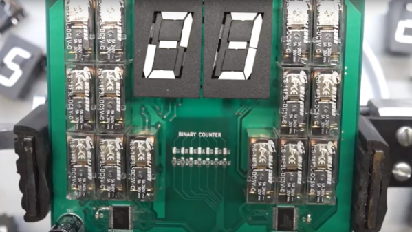
Undertaken as proof of concept before committing to a full six digit clock build, we’d say [ProtoG] is hitting the mark. Yes, it’s loud, but the sound is glorious. The video below shows the display being put through its paces, and when the clock rate ramps up, the rhythmic pulsations of the relays driving the seven-segment flip displays is hypnotizing. The relays, one per segment of the Alfa Zeta flip displays, have DPDT contacts wired to flip a segment by reversing polarity. As a work in progress, [ProtoG] hasn’t shared many more details yet, but he promises to keep us up to date on the converter aspect of the circuit. Right now it just seems like a simple but noisy driver. We’ll be following this one with interest.
If you prefer your clocks quieter but still like funky displays, check out this mixed media circus-themed clock.