Old Time Traffic Signal Revived With A Raspberry Pi Controller

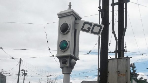
Anyone with even a passing familiarity with the classic animated shorts of the 1940s will recognize the traffic signal in the image above. Yes, such things actually existed in the real world, not just in the Looney world of [Bugs Bunny] et al. As sturdy as such devices were, they don’t last forever, though, which is why a restoration of this classic Acme traffic signal was necessary for a California museum. Yes, that Acme.

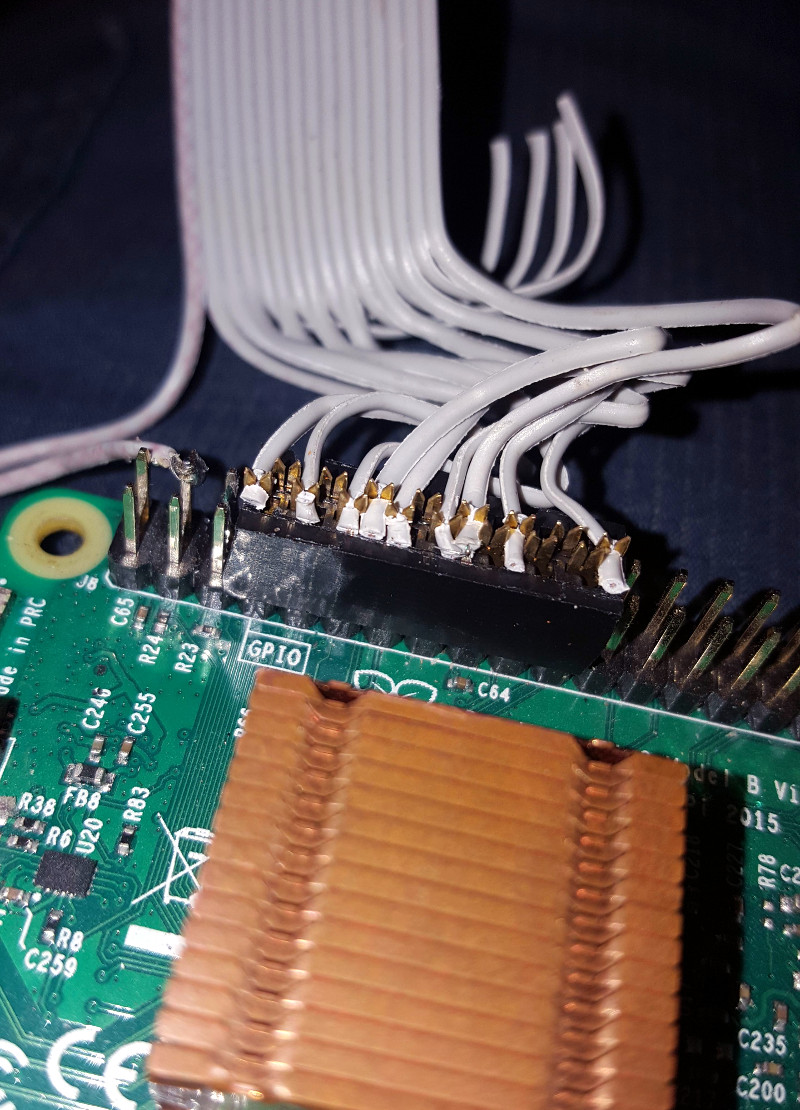
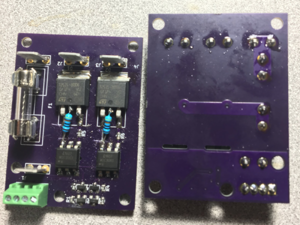
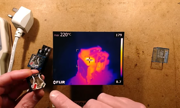
When you see a traffic signal from the early days of the automotive age like this one, it becomes quickly apparent how good the modern equivalent has become. Back in the day, with a mix of lights distributed all over the body of the signal, arms that extend out, and bells that ring when the state changes, it’s easy to see how things could get out of hand at an intersection. That complexity made the restoration project by [am1034481] and colleagues at the Southern California Traffic Museum all the more difficult. Each signal has three lights, a motor for the flag, and an annunciator bell, each requiring a relay. What’s more, the motor needs to run in both directions, so a reversing relay is needed, and the arm has a mechanism to keep it in position when motor power is removed, which needs yet another relay. With two signals, everything was doubled, so the new controller used a 16-channel relay board and a Raspberry Pi to run through various demos. To keep induced currents from wreaking havoc, zero-crossing solid state relays were used on the big AC motors and coils in the signal. It looks like a lot of work, but the end results are worth it.

Looking for more information on traffic signal controls? We talked about that a while back.

Smart Power Strip Revived With Raspberry Pi

We’re all for buying broken stuff from eBay to save yourself a few bucks: buy it cheap, fix it, and reap the rewards of being a step ahead of the average consumer. Searching through the “For parts or not working” categories is nearly the official pastime here at the Hackaday Bunker. But buying an eBay find only to have it give up the ghost in a couple weeks? That hurts.

That’s precisely what happened to [idaresiwins] when he bought this beefy looking “Web Power Switch” on the Electronic Bay. After two weeks, the controller board blew and his “smart” power strip became very stupid indeed. But with the addition of a Raspberry Pi, he’s got it back up and running. Not only that, but given the extra horsepower this device now contains, it now doubles as a basic server for the home lab.

This conversion was helped by the fact that the original controller was on a separate board from the relays, and connected with a small ribbon cable. All [idaresiwins] had to do was figure out which wire in the cable went to each of the eight relays, and fire them off with the Pi’s GPIO pins. In an interesting detail, he opened up one of the ends of the ribbon cable and used it as a punch down block of sorts to easily hook the wires up to the Pi’s pins. We might suggest some hot glue to keep everything from moving around, but otherwise it’s a neat tip.

[idaresiwins] found some information online about making a web-based GPIO interface, which he adapted to control the outlets on the power strip. He then wrapped the Pi up in plastic to keep it from shorting out, and tucked it inside the case. Note that he was able to pull 5 VDC from the relay board and run it to the Pi over the ribbon cable, so he didn’t need to bother with hacking a USB adapter in there.

Controlling AC devices over the Interwebs is an extremely popular project, and we’ve even seen a DIY device that looks quite similar to this product. Most of them are now using the ESP8266, but with the Pi onboard this hack is more like a super-sized version of the PowerPwn.

Card Reader Lockout Keeps Unauthorized Tool Users At Bay

It’s a problem common to every hackerspace, university machine shop, or even the home shops of parents with serious control issues: how do you make sure that only trained personnel are running the machines? There are all kinds of ways to tackle the problem, but why not throw a little tech at it with something like this magnetic card-reader machine lockout?

[OnyxEpoch] does not reveal which of the above categories he falls into, if any, but we’ll go out on a limb and guess that it’s a hackerspace because it would work really well in such an environment. Built into a sturdy steel enclosure, the guts are pretty simple — an Arduino Uno with shields for USB, an SD card, and a data logger, along with an LCD display and various buttons and switches. The heart of the thing is a USB magnetic card reader, mounted to the front of the enclosure.

To unlock the machine, a user swipes his or her card, and if an administrator has previously added them to the list, a relay powers the tool up. There’s a key switch for local override, of course, and an administrative mode for programming at the point of use. Tool use is logged by date, time, and user, which should make it easy to identify mess-makers and other scofflaws.

We find it impressively complete, but imagine having a session timeout in the middle of a machine operation would be annoying at the least, and potentially dangerous at worst. Maybe the solution is a very visible alert as the timeout approaches — a cherry top would do the trick!

There’s more reading if you’re one seeking good ideas for hackerspace. We’ve covered the basics of hackerspace safety before, as well as insurance for hackerspaces.

Continue reading “Card Reader Lockout Keeps Unauthorized Tool Users At Bay”

DIY SSR For Mains Switching

Typical power strips have their sockets tightly spaced. This makes it cumbersome to connect devices whose wall warts or power bricks are bulky — you end up losing an adjoining socket or two. And if the strip has a single power switch, you cannot turn off individual devices without unplugging them.

Planning to tackle both problems together, [Travis Hein] built himself some custom Dual SSR Controlled Socket Outlets for his workbench. He also decided to add remote switching ability so he could turn off individual sockets via a controller, Raspberry Pi, smartphone app or most ideally, a nice control panel on his desk consisting of a bank of switches.

The easiest solution for his problem would have been to just buy some off-the-shelf SSR or relay modules and wire them up inside his sockets. But he couldn’t find any with the features he wanted, and SSR’s were a little bit on the expensive side. Also, we wouldn’t have a project to write about – sometimes even the simple ones can show us a thing or two.

For starters, he walks us through a quick and simplified primer on figuring out thermal dissipation for the triacs which will be used on his boards. This is tricky since the devices are connected directly to utility voltage so he needs to take care of track clearances, mechanical separation as well as safety. However, for his first board prototypes, he did not add any heat sinking for the triacs, thereby limiting their use to low current loads. Since the SSR also needs to have a wide control voltage range, he describes how the two transistor constant-current input block works to limit opto-triac LED current over a range of 2 V to 30 V.

Before he moves on to his next prototype, [Travis] is looking for feedback to improve his design, make it safer, and figure out if it can pass safety protocols. Let him know via comments below.

Fake Omron Relays Are Worth What You Pay For Them

We love taking a look at fake components and [BigClive] has put together something really special in this category. When he saw he could buy suspiciously cheap Omron relays on eBay, he knew something must be fishy so he put in an order.

Some of the fakes he received are even marked Omrch instead of Omron, and your ear can detect the counterfeits by the varying sounds they make during operation. But of course [Clive’s] investigation goes much deeper than that. He started driving the relays to their rated voltages and taking temperatures with a FLIR camera.

The results were not surprising. At lower voltages the relays seemed to do okay, but closer to the maximums it’s obvious the components in the fakes are not rated for enough power to work. You can even see some charring of a resistor and its plastic holder from having too much power for the component’s rating. [Clive] actually replaced the errant resistor with a higher value resistor that reduces the current consumption and power dissipated.

He was also suspicious of the metal content of the contacts. You may think that doesn’t matter, but actually, the composition of relay contacts is critical to making reliable relay circuits. Depending on how much current flows and if the switching is dry (that is, made without current flowing) or not dictates use of different material.

The conclusion was that these relays might work for light duty projects, but for commercial projects or operating near the edge of the ratings, you want to give these a pass. If you do need a lot of low-power relays on the cheap — to compute a square root, or to build the whole computer — [Clive’s] process of testing and characterizing these fakes may come in handy for you.

Continue reading “Fake Omron Relays Are Worth What You Pay For Them”

Because Building A Relay Computer Isn’t Hard Enough

For this year’s Hackaday Prize, we’re doing something special. We’re introducing achievements for Prize projects. Think of them as merit badges. If your Hackaday Prize project has multiple parts that come together into one unified, awesome whole, you get the Voltron achievement. If you’ve built a musical instrument that unexpectedly blows everyone’s minds, you get the Diva Plavalaguna Achievement. A select few entries will earn the Pickle Rick achievement. What’s this? It’s a jaw-dropping build that makes you shake your head in the totality of engineering perfection.

Here’s a project that nails this achievement. It’s a homebrew computer, made out of relays, that runs a custom instruction set. It’s built on Brainf*ck. It is, by far, the most absurd and amazing homebrew computer you’ve ever seen.

Several modules on a shelf, for scale.

First, the hardware. This CPU is built out of about 800 Soviet reed relays, RES64, RES55, and RES-43 relays, if you want some part numbers. These relays are mounted on logic cards connected to a backplane. Each backplane consists of thirty-two of these cards, and it takes two backplanes to build up a 16-bit full adder. The 16-bit instruction pointer and 16-bit address pointer each fit on half a backplane.

Moving up one level, the instruction set for this computer is based on Brainf*ck, with a few additions. The ‘+’ instruction adds to the current value, the ‘>’ instruction still increases the current memory address, but there are a few new instructions that make this CPU not an interminable world of suffering. There’s now a ‘write current data value to register’ commands, and logical XOR instructions.

Have relay-based computers been done before? Yes, and so have Brainf*ck ISAs. The combination is rarely seen, and we’ve never seen one that performs this well. Below, you can see a video of this computer counting at 500 operations per second (or 500 Hz from a frequency counter). This is really unimaginable with any other relay computer we’ve seen, and it’s all thanks to those really tiny Soviet tubes. If you want a Hackaday Prize project that’s jaw-dropping, here you go.

Continue reading “Because Building A Relay Computer Isn’t Hard Enough”

This Is How The Fonz Would Play MP3s

Here at Hackaday, we love to see old hardware treated with respect. A lovingly restored radio or TV that’s part of our electronic heritage is a joy to behold, and while we understand the desire to stream media from a funky retro case, it really grates when someone throws away the original guts to make room for new electronics.

Luckily, this Seeburg jukebox wall remote repurposing is not one of those projects. [Scott M. Baker] seems to have an appreciation for the finer things, and when he scored this classic piece of Mid-Century Americana, he knew just what to do. These remotes were situated around diners and other hangouts in the 50s and 60s and allowed patrons to cue up some music without ever leaving their seats. They were real money makers back in the day, and companies put a lot of effort into making them robust and reliable.

[Scott]’s first video below shows the teardown of this unit; you can practically smell the old transformer and motor windings. His goal in the second video was to use the remote to control his Raspberry Pi jukebox; he wisely decided to leave everything intact and use the original electromechanically generated pulses to make selections. His analysis led to a nicely executed shield for his Pi which conditions the pulses and imitates coin drops; happily, the coin mechanism still works too, so you can still drop a quarter for a tune.

The remote is working well now, but [Scott] still needs to finish up a few odds and ends to bring this one home. But we love the look and the respect for tradition here, as we did when this juke got a Raspberry Pi upgrade to imitate a missing wall remote.

Continue reading “This Is How The Fonz Would Play MP3s”