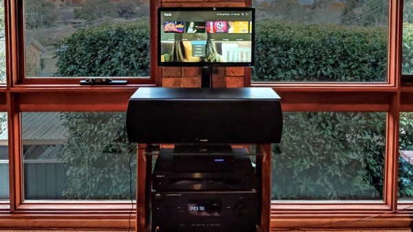
Despite appearances, [This Old Tony]’s latest series has little to do with CNC-ifying an Etch A Sketch. Although he certainly achieves that, more or less, automating the classic toy is just the hook for a thorough lesson in CNC machine building starting with the basics.
Fair warning: we said basics, and we mean it. [Old Tony]’s intended audience is those who haven’t made the leap into a CNC build yet and need the big picture. Part one concentrates on the hardware involved – the steppers, drivers, and controller. He starts with one of those all-in-one eBay packages, although he did upgrade the motion controller to a Mach4 compatible board; still, the lessons should apply to most hardware.
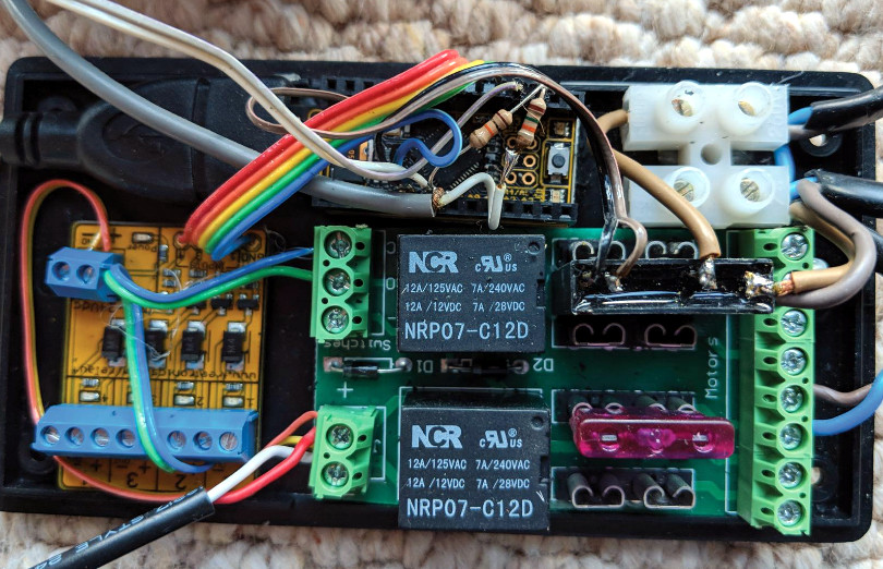
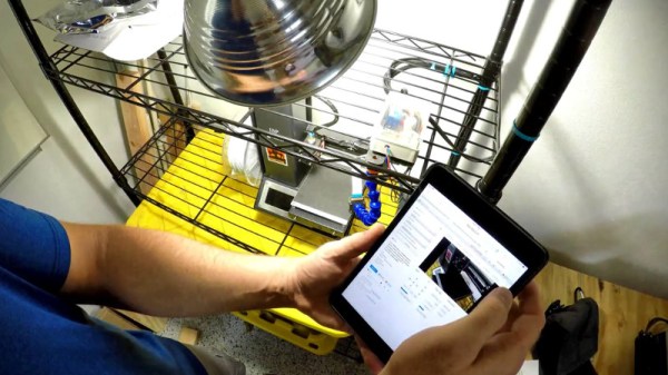
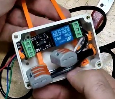
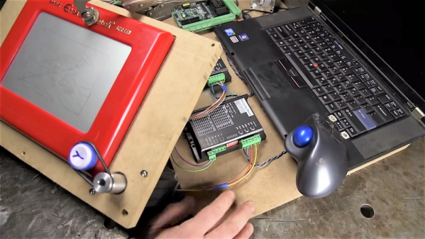
By the end of part one, the Etch A Sketch is connected to two of the steppers and everything is wired up and ready to go for part two, the first part of which is all about inputs and outputs. Again, this is basic stuff, like how relays work and why you might need to use them. But that’s the kind of stuff that can baffle beginners and turn them off to the hobby, so kudos to [Old Tony] for the overview. The bulk of the second part is about configuring Mach4 Hobby, with a ton of detail and some great tips and tricks for getting a machine ready to break some end mills.
For someone looking to get into a CNC build, [Old Tony]’s hard-won CNC experience really fills in the gaps left by other tutorials. And it looks like a third part, dealing with making all this into something more than an automated Etch A Sketch, is in the works. We’re looking forward to that.
Continue reading “The Complete Beginner’s Guide To Building A CNC Machine”