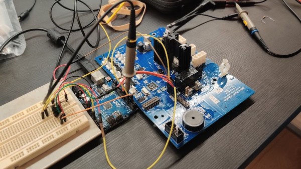
Tom Nardi and I had a good laugh this week on the Podcast when he compared the ECU hacks that enabled turning a VW with steering assist into a self-driver to a hack last week that modified a water cooler to fill a particular cup. But it’s actually no joke — some of the very same techniques are used in both efforts, although the outcome of one is life-and-death, and the other is just some spilled ice-cold water.
 This reminded me of Travis Goodspeed’s now-classic talk “In Praise of Junk Hacking” from way back in 2016. For background, this was a time when IoT devices and their security were in their relative infancy, and some members of the security community were throwing shade on the dissection of “mere” commercial crap. (Looked back on from today, where every other member of a Botnet is an IP camera, that argument didn’t age well.)
Travis’ response was that hacking on junk lets us focus on the process — the hack itself — rather than getting distracted by the outcome. Emotions run high when a security flaw affects millions of individuals, but when it’s a Tamagotchi or a pocket calculator, well, it doesn’t really matter, so you focus on the actual techniques. And as Travis points out, many of these techniques learned on junk will be useful when it counts. He learned about methods to defeat address-space randomization, for instance, from an old hack on the TI-85 calculator, which garbage-collected the variables that needed to be overwritten.
So I had junk hacking in the back of my mind when I was re-watching Hash Salehi’s great talk on his work reverse engineering smart meters. Funnily enough, he started off his reverse engineering journey eleven years ago with work on a robot vacuum cleaner’s LIDAR module. Junk hacking, for sure, but the same techniques taught him to work on devices that are significantly more serious. And in the craziest of Hackaday synergies, he even hat-tipped Travis’ talk in his video! Hacking is hacking!


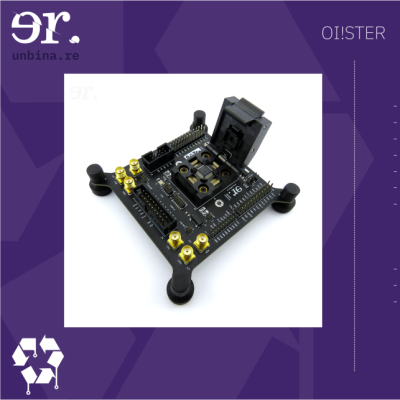 Unbinare’s tools are designed to work in harmony with each other, a requirement for any productive reverse-engineering effort. OI!STER is a general-purpose salvaged MCU research board, with sockets to adapt to different TQFP chip sizes. This board is Maurits’s experience in reverse-engineering condensed into a universal tool, including a myriad of connectors for different programming/debugging interfaces. We don’t know the board’s full scope, but the pictures show an STM32 chip inside the TQFP socket, abundant everywhere except your online retailer of choice. Apart from all the ways to break out the pins, OI!STER has sockets for power and clock glitching, letting you target these two omnipresent Achilles’ heels with a tool like ChipWhisperer.