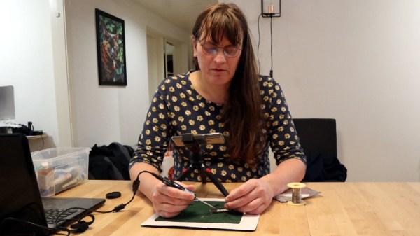
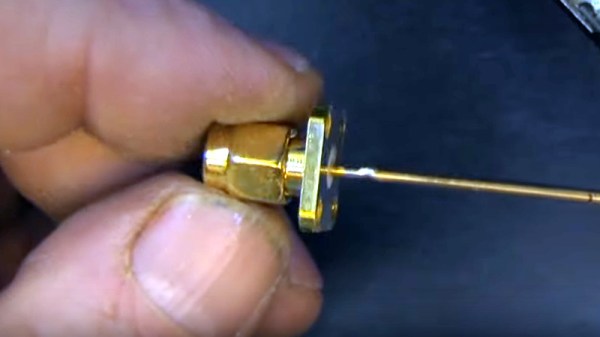
Using Your Phone As A Microscope On The Electronics Workbench

One aspect of working for Hackaday comes in our regular need to take good quality photographs for publication. I have a semi-decent camera that turns my inept pointing and shooting into passably good images, but sometimes the easiest and quickest way to capture something is to pull out my mobile phone.

It’s a risky step because phone camera modules and lenses are tiny compared to their higher quality cousins, and sometimes the picture that looks good on the phone screen can look awful in a web browser. You quickly learn never to zoom on a mobile phone camera because it’s inevitably a digital zoom that simply delivers grainy interpolated pictures.

That’s not to say that the zoom can’t be useful. Recently I had some unexpected inspiration when using a smartphone camera as a magnifier to read the writing on a chip. I don’t need an archival copy of the image… I just needed a quick magnifying tool. Have I been carrying a capable magnifier for soldering in my pocket or handbag for years without realising it? I decided to give it a try and it worked okay with a few caveats. While I have seen optics turn these cameras into pretty good microscopes, my setup added nothing more than a phone tripod, and will get you by in a pinch.

Continue reading “Using Your Phone As A Microscope On The Electronics Workbench”

Learn Bil Herd’s DIY Surface Mount Assembly Process

You can do your own Surface Mount Technology based PCB assembly with just a handful of tools and some patience. At the heart of my SMT process is stopping to inspect the various steps all while trying to maintain a bit of cleanliness in the process.

Surface mount or Surface Mount Technology (SMT) is the modern way to assemble Printed Circuit Boards (PCB) and is what is commonly seen when opening a modern piece of tech. It’s much smaller than the older Through-Hole (TH) technology where the component leads were inserted into holes in PCB, and act we called “stuffing” since we had to stuff the components into the holes.

A few specialized tools make this a lot easier, but resourceful hackers will be able to pull together a solder paste stencil jig, vacuum tweezers, and a modified toaster oven with a controller that can follow the reflow profile of the solder paste. Where you shouldn’t skimp is on the quality, age, and storage of the solder paste itself.

Join me after the break for my video overview of the process I use in my workshop, along with details of every step of my SMT assembly process.

Continue reading “Learn Bil Herd’s DIY Surface Mount Assembly Process”

Logitech Joystick Gets A Mechanical Sidekick

The mechanical keyboard rabbit hole is a deep one, and can swallow up as much money and time as you want to spend. If you’ve become spoiled on the touch and responsiveness of a Cherry MX or other mechanical switch, you might even start putting them on other user interfaces as well, such as this Logitech joystick that now sports a few very usable mechanical keys for the touch-conscious among us.

The Logitech Extreme 3D Pro that [ErkHal] and friend [HeKeKe] modified to accept the mechanical keys originally had a set of input buttons on the side, but these were unreliable and error-prone with a very long, inconsistent push. Soldering some mechanical switches directly on the existing board was a nice improvement, but the pair decided that they could do even better and rolled out an entire custom PCB to mount the keys more ergonomically. The switches are Kailh Choc V2 Browns and seem to have done a great job of improving the responsiveness of the joystick’s side buttons. If you want to spin up your own version, they’ve made the PCBs available on their GitHub page.

While [ErkHal] notes the switches aren’t the best and were only used since they were available, they certainly appear to work much better than what the joystick shipped with originally. In fact, we recently saw similar switches used to make a custom mechanical keyboard made for the PinePhone.

Exhaust Fan-Equipped Reflow Oven Cools PCBs Quickly

With reflow soldering, sometimes close is good enough. At the end of the day, the home gamer really just needs a hot plate or an old toaster oven and a calibrated Mark I eyeball to get decent results. This exhaust fan-equipped reflow oven is an attempt to take control of what’s perhaps the more challenging part of the reflow thermal cycle — the cool down.

No fan of the seat-of-the-pants school of reflow soldering, [Nabil Tewolde] started with a cast-off toaster oven for what was hoped to be a more precise reflow oven. The requisite temperature sensors and solid-state relays were added, along with a Raspberry Pi Zero W and a small LCD display. Adding the cooling assist started by cutting a gaping hole cut in the rear wall of the oven, which was then filled with a short stretch of HVAC duct and a stepper-controlled damper. The far end of the duct was fitted with a PC cooling fan; while it seems sketchy to use a plastic fan to eject hot air from the oven, [Nabil] says the exhaust isn’t really that hot by the time it gets to the fan. At the end of the reflow phase of the thermal profile, the damper opens and the fan kicks on, rapidly cooling the oven’s interior.

Unfortunately, [Nabil] still needs to crack open the oven door to get decent airflow; seems like another damper to admit fresh air would help with that. That would complicate things a bit, but it still wouldn’t be as over-the-top as some reflow builds we’ve seen. Then again, that calibrated eyeball thing can work pretty well too, even without a toaster oven.

Continue reading “Exhaust Fan-Equipped Reflow Oven Cools PCBs Quickly”

SMD Challenge Extreme Edition Gets Our Flux Flowing

Skills challenges have become a fun way to facilitate friendly competition amongst anyone who appreciates a fine solder joint. If you’ve seen any Supercon / Remoticon coverage there’s surely been a mention of the infamous soldering skills challenge, where competitors test their mettle against surface mount components sized to be challenging but fair. What if there was a less friendly SMD challenge designed to make you hold your breath lest you blow the components away? Well now there is, the SMD Challenge Extreme Edition by friend-of-the-Hackaday and winner of the 2019 Supercon soldering challenge [Freddie].

When assembled the SMD Extreme Edition uses a 555 timer and a 74HC4017 decade counter to light a ring of 10 LEDs lights around its perimeter, powered by a coin cell. However the  Extreme Edition deviates from the typical SMD Challenge format. Instead of ramping up in difficulty with ever-shrinking components, the Extreme Edition only has one size: torturous. See those gray blobs in the title image? Those are grains of rice.

The Extreme Edition’s 0201-sized LEDs aren’t the absolute smallest components around, but to minimize enjoyment all passives are 01005. (Check out the SMD Challange Misery Edition for even 01005 LED action.)

The Extreme Edition has other tricks up its sleeve, too. That 555 may be venerable in age, but this version is in an iron-frustrating 1.41 x 1.43 mm BGA package, which pairs nicely with that decade counter in 2.5 mm x 3.5 mm QFN.

Despite the wordwide pandemic locking down travel and conferences, a few brave challengers have already taken up their iron and succeeded at Extreme SMD. Want to see it in action? Check out the original Tweets after the break.

Continue reading “SMD Challenge Extreme Edition Gets Our Flux Flowing”

Magnifying On The Cheap

If there is one thing we’ve learned during several years of running the Hackaday SMD soldering challenge it is this: Most people need magnification to do good soldering at a tiny scale. The problem is, like most tools, you can buy something as cheap as a $5 binocular headset or you can spend $1,000 or more on a serious microscope. What’s in between? [Noel] looks at some affordable options in a recent video that you can see below.

[Noel] started out with a cheap “helping hand” that has a simple little magnifying glass attached to it. The major criterion was to find something that would have no delay so he could solder under magnification. While it is possible to work under a scope with a little lag in the display, it is frustrating and there are better options.

Continue reading “Magnifying On The Cheap”

Robotics Club Teaches Soldering

Oregon State University must be a pretty good place to go to school if you want to hack on robots. Their robotics club, which looks active and impressive, has a multi-part video series on how to solder surface mount components that is worth watching. [Anthony] is the team lead for their Mars Rover team and he does the job with some pretty standard-looking tools.

The soldering station in use is a sub-$100 Aoyue with both a regular iron and hot air. There’s also a cheap USB microscope that looks like it has a screen, but is covered in blue tape to hold it to an optical microscope. So no exotic tools that you’d need a university affiliation to match.

Continue reading “Robotics Club Teaches Soldering”