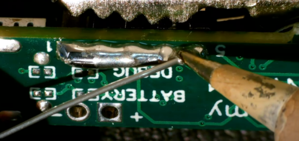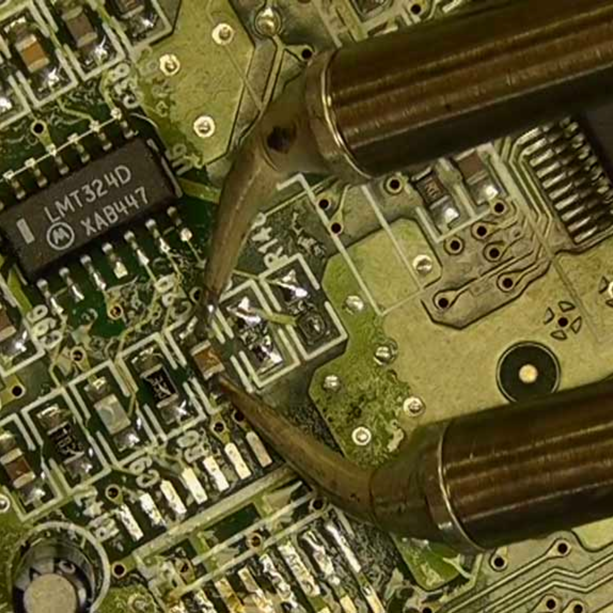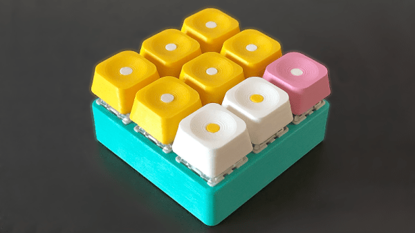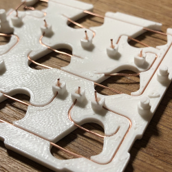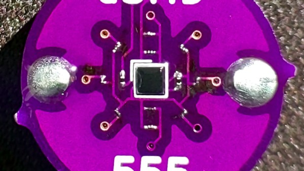
A highlight of last year’s Hackaday Remoticon was a soldering competition that had teams from around the world came together online and did the well-known MakersBox SMD Challenge kit in which a series of LED circuits of decreasing size must be soldered. The Hackaday crew acquitted themselves well, and though an 01005 resistor and LED certainly pushes a writer’s soldering skills to the limit it’s very satisfying to see it working. Lest that kit become too easy, [Arthur Benemann] has come up with something even more fiendish; his uSMD is a 555 LED flasher that uses a BGA 555 and a selection of 008004 small components.
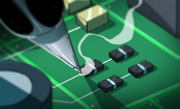
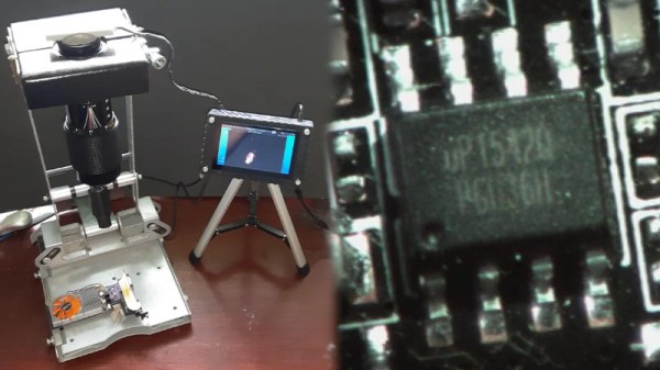
The trick with an 01005 is to heat not the tinned and fluxed solder joint, but the trace leading up to it. If components of that size can be mastered then perhaps an 008004 isn’t that much smaller so maybe the same technique might work for them too. In his tip email to us he wrote “Soldering 008004 isn’t much worse than a 0201, you just need magnification“, and while we think he might be trolling us slightly we can see there’s no reason why it shouldn’t be do-able. Sadly he doesn’t seem to have made it available for us to buy and try so if you want to prove yourself with a soldering iron you’ll have to source the PCBs and parts yourself. Still, we suspect that if you are the type of person who can solder an 008004 then that will hardly be an onerous task for you.
Meanwhile this isn’t the first soldering challenge kit we’ve brought you, and of course if you’d like to hone your skills you can find the MakersBox one on Tindie.