An Amazing DIY Single Board ARM Computer With BGA

DIY Single Board Computer ARM

Typically, you buy a single board Linux computer. [Henrik] had a better idea, build his own ARM based single board computer! How did he do it? By not being scared of ball grid array (BGA) ARM processors.

Everyone loves the Raspberry Pi and Beagle Board, but what is the fun in buying something that you can build? We have a hunch that most of our readers stay clear of BGA chips, and for good reason. Arguably, one of the most important aspects of [Henrik’s] post is that you can easily solder BGAs with cheaply available tools. OSH Park provides the inexpensive high-quality PCBs, OSH Stencils provides the inexpensive stencils, and any toaster oven allows you to solder even the most difficult of components. Not only does he go over the PCB build, he also discusses the bootloader, u-boot, and how to get Linux running.

Everything worked out very well for [Henrik]. It’s a good thing too, cause we sure wouldn’t want to debug a PCB as complicated as this one. What projects have you built that use a BGA? Let us know how it went!

Solder Stencil

How To Laser Cut Mylar Solder Stencils

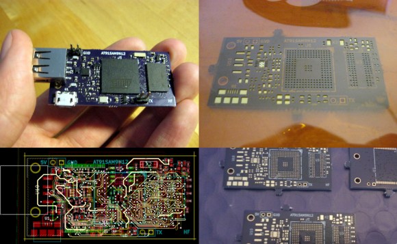
When you think about the difficulties of working with surface mount components, the first thing that often comes to mind is trying to solder those tiny little parts. Instead of soldering those parts by hand, you can actually apply solder paste to the pads and place all of the components on at once. You can then heat up the entire board so all of the parts are soldered simultaneously. It sounds so much easier! The only problem is you then need a solder stencil. You somehow have to get a thin sheet of material that has a perfectly sized hole where all of your solder pads are. It’s not exactly trivial to cut them out by hand.

[Juan] recently learned a new trick to make cutting solder stencils a less painful process. He uses a laser cutter to cut Mylar sheets into stencils. [Juan] appears to be using EagleCAD and Express PCB. Both tools are available for free to hobbyists. The first step in the process is to export the top and bottom cream layers from your CAD software.

The next step is to shrink the size of the solder pads just a little bit. This is to compensate for the inevitable melting that will be caused by the heat from the laser. Without this step, the pads will likely end up a little bit too big. If your CAD software exports the files as gerbers, [Juan] explains how to re-size the pads using ViewMate. If they are exported as DXF files, he explains how to scale them using AutoCAD. The re-sized file is then exported as a PDF.

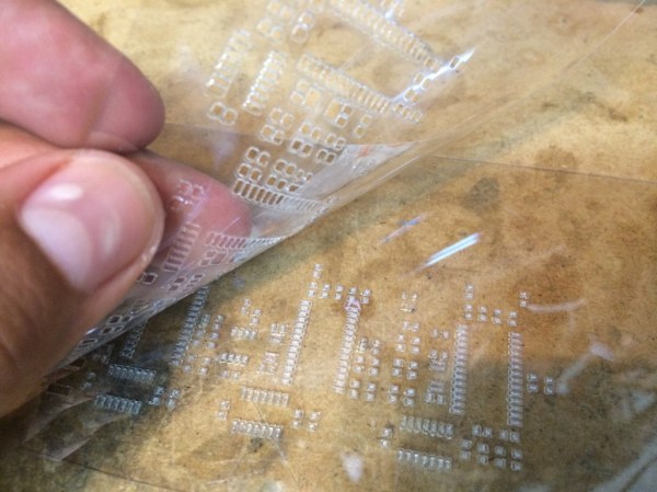
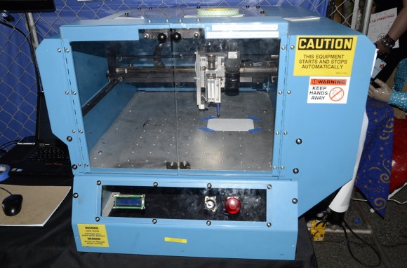
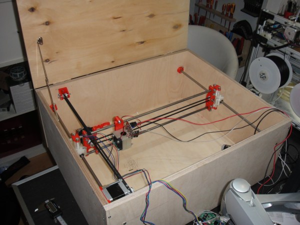
[Juan’s] trick is to actually cut two pieces of 7mil Mylar at the same time. The laser must be calibrated to cut all the way through the top sheet, but only part way into the bottom piece. The laser ends up slightly melting the edges of the little cut out squares. These then get stuck to the bottom Mylar sheet. When you are all done cutting, you can simply pull the sheets apart and end up with one perfect solder stencil and one scrap piece. [Juan] used a Full Spectrum 120W laser cutter at Dallas Makerspace. If you happen to have this same machine, he actually included all of the laser settings on his site.

LIB3 Plans To Bring Contract Manufacturing To The Masses

LIB3's paste system
LIB3’s paste system

LIB3 is an open source hardware start-up from upstate New York. Thus far, the team has made some interesting products such as the piLED kit. However, they have big dreams for the future. LIB3 plans to become a contract assembly house specifically targeting low volume makers. To do this they have to build their own tools. LIB3’s latest project is a solder paste dispenser for surface mount components. Traditionally solder paste is applied with stencils made of stainless steel. In more recent years laser cut kapton has become a favorite for low volume production.

Both of these systems require a stencil to be made up. LIB3 took a different approach, and modified an old CNC glue dispenser for paste. The team got their hands on an 1991 vintage X/Y glue dispensing system. X/Y systems in this era were big, heavy affairs with powerful motors. LIB3 removed all the control electronics and built their own system from scratch. New features include direct computer control, and a vision system.

Continue reading “LIB3 Plans To Bring Contract Manufacturing To The Masses”

Graffiti Briefcase For Stealth Tagging

We’re floored by painter and engineer [Bob Partington’s] graffiti briefcase, which proves how well art and tech can complement one another. Fear not, Arduino haters, [Bob]’s case is an analog dream: no microcontrollers here.

The guts consist of 2 components: a linear drive system and a trigger assembly. The former takes advantage of a small RC motor with a chain drive which slides the can’s mounting unit along two stainless steel rods. The latter includes a custom wound solenoid plugged into a 24V cordless drill battery, which slams down 5 pounds of force onto the can’s nozzle to fire the paint.

This all fits into an otherwise inconspicuous looking briefcase to provide some urban camouflage. The final component is a stencil, which slides into a rectangular hole on the bottom of the case. The paint can sprays downward through the stencil and tags the ground at the touch of a brass button located near the handle.  [Bob] has plenty of other cool inventions you should check out that are less illegal. Or, stick it to the man by automating your tagging with Time Writer.

Continue reading “Graffiti Briefcase For Stealth Tagging”

The Definitive Guide To Solder Stencils

Yes, we’ve seen our share of tutorials for making solder paste stencils, but [Felix] hit it out of the park with this one. It’s the definitive guide to making solder stencils at home, with quality as good as you would find in any professionally made stencil.

The material for the stencils comes from the same source as so many other DIY solder stencils – aluminium cans. The interior plastic coating and the exterior paint job are both removed with heat, acetone, and patience. After laying out the cream layer of his board in a PDF file, [Felix] used a fairly interesting transfer medium to get the toner onto the aluminum; cheap vinyl shelving paper attached to a piece of paper apparently makes for an ideal surface to transfer toner.

After transfer, the board is etched with HCl and peroxide. [Felix] is getting some very good results with his method, including a few very fine pitch IC footprints. It’s just as good as a professionally made, laser cut stainless stencil, and you probably already have all the necessary ingredients lying around your house. That’s a win anytime.

Machining Beer Can Solder Stencils

This is a solder paste stencil machined from a beer can. [Simon Ludborzs] spent quite a bit of time dialing in his process to get to this point. Note the nice crisp edges of the openings. That’s a big change from his first attempt.

When looking for a way to make his own stencils he considered two options: plastic and aluminum. He produced both (more about the plastic stencil and his reflow process is discussed in this post). Plastic is a bit easier to work with since it lays flat. But it proves to be too thick. After applying paste with a squeegee there’s way too much solder on the pads. Aluminum beverage can walls are much thinner, depositing less paste.

We’ve seen soda cans used in the past, but they were produced through an etching process. [Simon] cut these holes using a CNC mill. This required a bit of futzing to figure out the right settings. For instance, he used Altium to produce CAM files from his circuit design. But the program is set up to mill the outside of traces, resulting in openings that are too large. He fixed this by setting the pasted expansion rule in the program to a negative value. The other advantage to using a mill is that he can cut precision tooling holes to ensure proper alignment. You can see them in the upper corners of this image.

DIY Laser Cutter Built To Make Stencils

It was time for some new T-shirts so [Andreas Hölldorfer] built a laser cutter. Wait, what? That’s the excuse he’s going with, and in the end this scratch built laser cutter did come in handy by cutting stencils to use when decorating his garments.

The first thing we thought when looking at the cutter is where’s the tube? [Andreas] didn’t use a CO2 laser, so this ends up being rather low-powered. The cutting head is a 1W blue laser diode which manages to slice the three-ring binder separator pages he’s using for the stencils. The two-axis machine is mounted inside a wooden box to protect his eyes while it’s cutting. He plans to add a drawer later on so that the cutting bed will slide in and out to swap out material for the next project. He already does a lot of 3D printing work and had an old RepRap driver board on hand to use for this projects. He designed and printed the red mounting brackets which make all of the junk-bin components work together. Not bad!

If you’d like to try this out on a smaller scale try using optical drive parts for the axes.