EPROM Timer

[glitch] had a cheap EPROM eraser with very few features. Actually, that might be giving it too much credit: it’s barely more than a UV light that turns on when it’s plugged in and turns off when it’s plugged out unplugged. Of course it would be nice to implement some safety features, so he decided he’d hook it up to a software-controlled power outlet.

Of course, controlling a relay that’s wired to mains is old hat around here, and in fact, we’ve covered [glitch]’s optoisolated mains switch already. He’s gone a little beyond the normal mains relay project with this one, though. Rather than use a microcontroller to run the relay, [glitch] wrote a simple Ruby script on his computer to turn the EPROM eraser on for the precise amount of time that is required to erase the memory.The Ruby script drives the relay control directly over a USB to serial adapter’s RTS handshake pin.

[glitch]’s hack reminds us that if you just need a quick couple bits of slow output, a USB-serial converter might be just the ticket. You could imagine driving everything from standard lamps to your 3D printer’s bed heater (provided you use similar hardware), but it’s especially helpful for [glitch] who claims to forget to turn off the eraser when it’s done its job, which leaves a potentially dangerous UV source just lying about. It’s always a good idea to add safety features to a dangerous piece of equipment!

USB Switch

Reverse Engineering How A USB Switch Switches

[Daniel] found himself with a need to connect a single USB device to two Linux servers. After searching around, he managed to find an inexpensive USB switch designed to do just that. He noticed that the product description mentioned nothing about Linux support, but he figured it couldn’t be that hard to make it work.

[Daniel] started by plugging the device into a Windows PC for testing. Windows detected the device and installed an HID driver automatically.  The next step was to install the control software on the Windows system. This provided [Daniel] with a tray icon and a “switch” function. Clicking this button disconnected the HID device from the Windows PC and connected the actual USB device on the other side of the USB switch. The second computer would now have access to the HID device instead.

[Daniel] fired up a program called SnoopyPro. This software is used to inspect USB traffic. [Daniel] noticed that a single message repeated itself until he pressed the “switch” button. At that time, a final message was sent and the HID device disconnected.

Now it was time to get cracking on Linux. [Daniel] hooked up the switch to a Linux system and configured a udev rule to ensure that it always showed up as /dev/usbswitch. He then wrote a python script to write the captured data to the usbswitch device. It was that simple. The device switched over as expected. So much for having no Linux support!

The In-Circuit SD Card Switch

SDISP

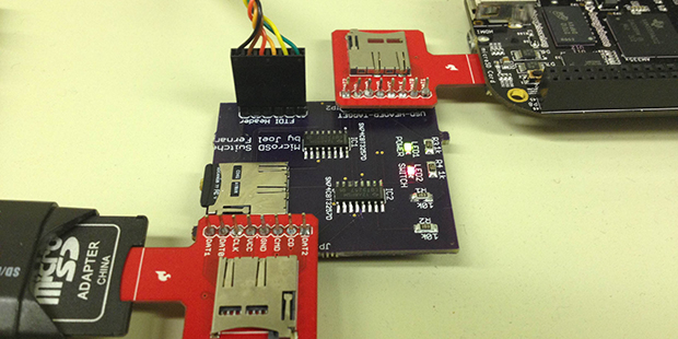
For nearly every problem, it’s possible to engineer a solution, even if you’re dealing with an extraordinarily niche problem that might only apply to yourself. [Joel] wanted to be able to program the microSD card in his BeagleBone with a new bootloader or file system without removing the SD card from the target board. This is a peculiar requirement, and it’s highly doubtful a product or even a circuit exists for such a function. This meant [Joel] would need to roll his own board to accomplish the task.

The board is remarkably simple, housing a single microSD socket, two expansion headers for a microSD sniffer for a computer and an embedded board, an FTDI header, and a pair of 4-bit multiplexer/demultiplexers. The operation of the device is fairly straightforward: send a signal down the FTDI cable, and the board switches the onboard SD card from one device to another.

[Joel] has a video of his screen that shows him pulling off in-circuit SD card reading and writing. You can check that out below.

Continue reading “The In-Circuit SD Card Switch”

DIY Pressure Plate Switch For Your Haunted House

Pressure Plate

Yes, its Halloween time again and the hacks are going to be crawling out of the woodwork for the rest of the month. [Rich Osgood] is off to a good start promising one hack every week until Halloween. Judging from this first project, a DIY pressure plate switch, we think there’s going to be a common theme to follow. [Rich] constructs his pressure plate for almost no cost using cardboard, tinfoil and duct tape. It couldn’t be easier, so make lots of these if your haunting project requires pressure plate triggers to activate any spooks. Judging by the cardboard construction it’s likely they will fail after multiple uses, but you can switch one out quickly requiring only two hookup wires and a bit of tape.

Hopefully we aren’t stealing [Rich’s] thunder by recommending using Xbee wireless remote sensors to covertly monitor guests or trigger spooktacular scares.

We will be keeping an eye out for [Rich’s] follow-up Halloween hacks. Join us after the break to watch the tutorial video on making homemade pressure plates.

Continue reading “DIY Pressure Plate Switch For Your Haunted House”

Rotary Phone Museum Exhibit

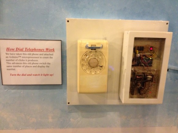
dial-telephone-museum-exhibit[David Burroughs] wrote in to share this dial telephone museum exhibit he built and we’re glad he did because we love interactive museum hacks. He mentions that it’s not really tied to the theme of the Roads and Rails Museum in which it’s installed. But when we think of railroad history we also think of telegraph. And that’s just a hop, skip, and a jump from telephones.

The display allows museum goers to play with the rotary dial on the phone. The box next two it contains a 10-position relay increment switch. So each pulse from the dial increments the switch. There’s a satisfying click, a moving arm, and different colored LEDs which highlight the inner workings. An Arduino board monitors the phone, displaying the dialed number on a seven segment display then incrementing the relay.

We figure the interesting part is to see that telephony used to use mechanical switching like this. But the video below includes a story about the kid who asked how you carried this phone around. This brings to mind the phrase “hang up the phone”, which doesn’t have the same literal meaning it used to.

Continue reading “Rotary Phone Museum Exhibit”

Viscerally Pleasing Electromechanical Doorbell

steam-punk-doorbell

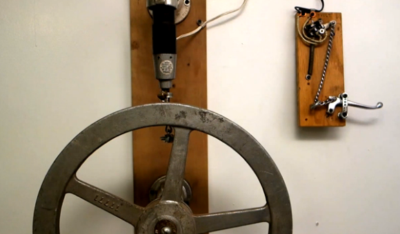
Sure, we could just slap the steam-punk label on this doorbell hack, but we think that cheapens it. The rig uses a combination of mercury switch and creative mechanics to form a doorbell. And we think it goes beyond aesthetics to a statement of who you are starting with the front door of your house. No wonder [Nick Normal] has moved it along with him from home to home over the years.

The portion to the right is the ringer itself. Pulling on the lever moves the chain through an eyelet to affect the mercury switch mounted above. That switch completes the circuit which drives the motor on the “bell” unit. We use quotes because instead of ringing a bell it’s striking the large valve control wheel which looks like it came straight from the same industrial plant where The Joker took his unfortunate fall into a vat of acid.

This certainly gives you something to aspire to. And if you think you’ve already achieved a doorbell setup on similarly-geeky footing why haven’t you tipped us off about it?

Hacking A PAL SNES To Output 50Hz Or 60Hz With A Single Switch

snes-pal-ntsc-mod

[Derecho] grabbed a PAL format Super Nintendo but wanted to make it play nicely with a 60 Hertz NTSC screen. His hack added a single switch to choose between 50 Hz and 60 Hz.

Take a look at the image above to see his alterations to the mainboard. The jumpers soldered to the two chips at the top are by far the trickiest part of the project. Each of the pins he soldered to needed to first be lifted from the PCB pad so that they no longer make contact with the etched traces. The technique he used involves heating the pin with an iron, then gently lifting it with a pin or a razor knife/blade. If you’ve got some experience populating SMD boards with a handheld iron this shouldn’t prove too difficult. The rest of the hack involves adding a 3-position switch (along with a 2k2 resistor) to choose between output modes based on what format game is being played.