Retrotechtacular: Soldering The Tek Way

For a lot of us, soldering just seems to come naturally. But if we’re being honest, none of us was born with a soldering iron in our hand — ouch! — and if we’re good at soldering now, it’s only thanks to good habits and long practice. But what if you’re a company that lives and dies by the quality of the solder joints your employees produce? How do you get them to embrace the dark art of soldering?

If you’re Tektronix in the late 1970s and early 1980s, the answer is simple: make in-depth training videos that teach people to solder the Tek way. The first video below, from 1977, is aimed at workers on the assembly line and as such concentrates mainly on the practical aspects of making solid solder joints on PCBs and mainly with through-hole components. The video does have a bit of theory on soldering chemistry and the difference between eutectic alloys and other tin-lead mixes, as well as a little about the proper use of silver-bearing solders. But most of the time is spent discussing the primary tool of the trade: the iron. Even though the film is dated and looks like a multi-generation dupe from VHS, it still has a lot of valuable tips; we’ve been soldering for decades and somehow never realized that cleaning a tip on a wet sponge is so effective because the sudden temperature change helps release oxides and burned flux. The more you know.

The second video below is aimed more at the Tek repair and rework technicians. It reiterates a lot of the material from the first video, but then veers off into repair-specific topics, like effective desoldering. Pro tip: Don’t use the “Heat and Shake” method of desoldering, and wear those safety glasses. There’s also a lot of detail on how to avoid damaging the PCB during repairs, and how to fix them if you do manage to lift a trace. They put a fair amount of emphasis on the importance of making repairs look good, especially with bodge wires, which should be placed on the back of the board so they’re not so obvious. It makes sense; Tek boards from the era are works of art, and you don’t want to mess with that.

Continue reading “Retrotechtacular: Soldering The Tek Way”

Close Shave For An Old Oscilloscope Saved With A Sticky Note

When you tear into an old piece of test equipment, you’re probably going to come up against some surprises. That’s especially true of high-precision gear like oscilloscopes from the time before ASICs and ADCs, which had to accomplish so much with discrete components and a lot of engineering ingenuity.

Unfortunately, though, those clever hacks that made everything work sometimes come back to bite you, as [Void Electronics] learned while bringing this classic Tektronix 466 scope back to life. A previous video revealed that the “Works fine, powers up” eBay listing for this scope wasn’t entirely accurate, as it was DOA. That ended up being a bad op-amp in the power supply, which was easily fixed. Once powered up, though, another, more insidious problem cropped up with the vertical attenuator, which failed with any setting divisible by two.

With this curious symptom in mind, [Void] got to work on the scope. Old analog Tek scopes like this use a bank of attenuator modules switched in and out of the signal path by a complex mechanical system of cams. It seemed like one of the modules, specifically the 4x attenuator, was the culprit. [Void] did the obvious first test and compared the module against the known good 4x module in the other channel of the dual-channel scope, but surprisingly, the module worked fine. That meant the problem had to be on the PCB that the module lives on. Close examination with the help of some magnification revealed the culprit — tin whiskers had formed, stretching out from a pad to chassis ground. The tiny metal threads were shorting the signal to ground whenever the 4x module was switched into the signal path. The solution? A quick flick with a sticky note to remove the whiskers!

This was a great fix and a fantastic lesson in looking past the obvious and being observant. It puts us in the mood for breaking out our old Tek scope and seeing what wonders — and challenges — it holds.

Continue reading “Close Shave For An Old Oscilloscope Saved With A Sticky Note”

Hackaday Links Column Banner

Hackaday Links: September 1, 2024

Why is it always a helium leak? It seems whenever there’s a scrubbed launch or a narrowly averted disaster, space exploration just can’t get past the problems of helium plumbing. We’ve had a bunch of helium problems lately, most famously with the leaks in Starliner’s thruster system that have prevented astronauts Butch Wilmore and Suni Williams from returning to Earth in the spacecraft, leaving them on an extended mission to the ISS. Ironically, the launch itself was troubled by a helium leak before the rocket ever left the ground. More recently, the Polaris Dawn mission, which is supposed to feature the first spacewalk by a private crew, was scrubbed by SpaceX due to a helium leak on the launch tower. And to round out the helium woes, we now have news that the Peregrine mission, which was supposed to carry the first commercial lander to the lunar surface but instead ended up burning up in the atmosphere and crashing into the Pacific, failed due to — you guessed it — a helium leak.
Continue reading “Hackaday Links: September 1, 2024”

An Oscilloscope For The Nuclear Age

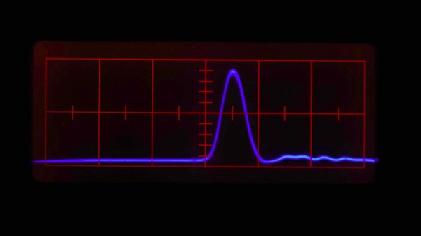
Here at Hackaday, we’re suckers for vintage instruments. More than one of our staffers has a bench adorned with devices spanning many decades, and there’s nothing more we like reading about that excursions into the more interesting or unusual examples. So when a Tweet comes our way talking about a very special oscilloscope, of course we have to take a look! The Tektronix 519 from 1962 has a 1GHz bandwidth, and [Timothy Koeth] has two of them in his collection. His description may be a year or two old, but this is the kind of device for which the up-to-the-minute doesn’t matter.

A modern 1GHz oscilloscope is hardly cheap, but is substantially a higher-speed version of the run-of-the-mill ‘scope you probably have on your bench. Its 1962 equivalent comes from a time when GHz broadband amplifiers for an oscilloscope input were the stuff of science fiction. The 519 takes the novel approach of eschewing amplification or signal conditioning and taking the input directly to the CRT deflection plates. It thus has a highly unusual 125Ω input impedance, and its feed passes through a coiled coaxial delay line to give the trigger circuits time to do their job before going into the CRT and then emerging from it for termination. It thus has a fixed deflection in volts per centimeter rather than millivolts, and each instrument has the calibration of its CRT embossed upon its bezel.

The 519 would not have been a cheap instrument in 1962, and it is no accident that there are reports of many of them coming back to Tek for service with radioactive contamination from their use in Government projects. We can’t help wondering whether the Russian equivalent super-high-speed ‘scope used the same approach, though we suspect we’ll never know.

If vintage Tek is your thing, have a look at their PCB manufacture from the 1960s.

Thanks [Luke Weston] for the tip.

Decimal Oscilloclock Harks Back To 1927 Movie

Metropolis is a classic, silent film produced in 1927 and was one of the very first full length feature films of the science fiction genre, and very influential. (C-3PO was inspired by Maria, the “Machine human” in Metropolis.) Within the first couple of minutes in the film, we get to see two clocks — one with a 24-hour dial and another larger one with a 10-hour dial. The human overlords of Metropolis lived a utopian 24 hour day, while the worker scum who were forced to live and work underground, were subjected to work in two ten-hour shifts during the same period.

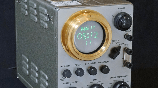
[Aaron]’s client was setting up a Metropolis themed man-cave and commissioned him to build a Metropolis Oscilloclock which would not only show the 24 hour and 10 hour clocks from the film, but also accurately reproduce the clock movements and its fonts. [Aaron]’s Oscilloclock is his latest project in the series of bespoke CRT clocks which he has been building since he was a teen.

The clock is built around a Toshiba ST-1248D vintage oscilloscope that has been beautifully restored. There are some modern additions – such as LED glow indicators for the various valves and an external X-Y input to allow rendering Lissajous figures on the CRT. He’s also added some animations derived from the original poster of the film. Doing a project of this magnitude is not trivial and its taken him almost eight months to bring it from concept to reality. We recommend looking through some of his other blog posts too, where he describes how oscilloclocks work, how he builds the HV power supplies needed to drive the CRT’s, and how he ensures vibration and noise damping for the cooling fans used for the HV power supplies. It’s this attention to detail which results in such well-built clocks. Check out some of [Aaron]’s other awesome Oscilloclock builds that we have featured over the years.

The film itself has undergone several restoration attempts, with most of it being recovered from prints which were discovered in old archives. If you wish to go down that rabbit hole, check out Wikipedia for more details and then head over to YouTube where several versions appear to be hosted.

Continue reading “Decimal Oscilloclock Harks Back To 1927 Movie”