Watering the garden or the lawn is one of those springtime chores that is way more appealing early in the season than later. As the growing season grinds along, a chore that seemed life-giving and satisfying becomes, well, just another chore, and plants often suffer for it.
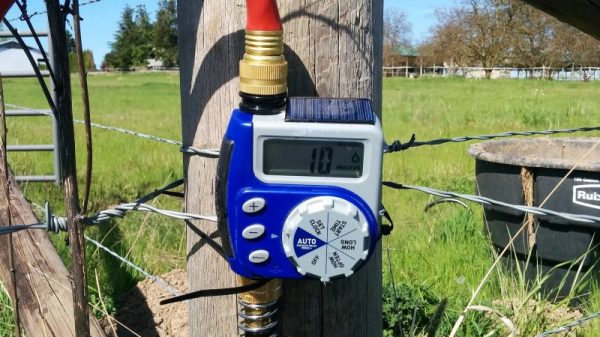
Automating the watering task can be as simple as buying a little electronic timer valve that turns on the flow at the appointed times. [A1ronzo] converted his water hose timer to solar power. Most such timers are very similar, with a solenoid-operated pilot valve in line with the water supply and an electronic timer of some sort. The whole thing is quite capable of running on a pair of AA batteries, but rather than wasting money on new batteries several times a season, he slipped a LiPo pack and a charge controller into the battery case slot and connected a small solar panel to the top of the controller.
The LiPo is a nominal 3.7-volt pack, so he did a little testing to make sure the timer would be OK with the higher voltage. The solar panel sits on top of the case, and the whole thing should last for years. And bonus points for never having to replace a timer that you put away at the end of the season with batteries still in it, only to have them leak. Ask us how we know.
Like the best of hacks, this one is quick, easy and cheap — $15 in parts, aside from the timer. There are more complicated irrigation solutions, of course, one of which even won the Hackaday Prize once upon a time. But this one has us ordering parts to build our own right now.