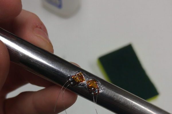
Cheap Torque Sensor Goes Back To Basics On Strain Gauges

Sooner or later, we’ve all got to deal with torque measurement. Most of us will never need to go beyond the satisfying click of a micrometer-style torque wrench or the grating buzz of a cordless drill-driver as the clutch releases. But at some point you may actually need to measure torque, in which case this guide to torque sensors might be just the thing.

[Taylor Schweizer]’s four-part series on torque is pretty comprehensive. The link above is to the actual build of his DIY torque transducer, but the preceding three installments are well worth the read too. [Taylor] describes himself as an e-waste connoisseur and tantalizes us with the possibility that his build will be with salvaged parts, but in the end a $20 bag of strain gauges and an LM358 were the quickest way to his proof of concept. The strain gauges were super-glued to a socket extension, hot glue was liberally applied for insulation and strain relief, and the whole thing wired up to a Teensy for data capture. A quick script and dump of the data to Excel and you’ve got a way to visualize torque.

An LCD display for real-time measurements is in the works, as are improvements to the instrumentation amp – for which [Taylor] might want to refer to [Bil Herd]’s or [Brandon Dunson]’s recent posts on the subject.

[via r/arduino]

High Tech, Low Cost Digital Torque Meter

Ever obsessed with stripping the hype from the reality of power tool marketing, and doing so on the cheap, [arduinoversusevil] has come up with a home-brew digital torque meter that does the job of commercial units costing hundreds of times as much.

For those of us used to [AvE]’s YouTube persona, his Instructables post can be a little confusing. No blue smoke is released, nothing is skookum or chowdered, and the weaknesses of specific brands of tools are not hilariously enumerated. For that treatment of this project, you’ll want to see the video after the break. Either way you choose, he shows us how a $6 load cell and a $10 amplifier can be used to accurately measure the torque of your favorite power driver with an Arduino. We’ve seen a few projects based on load cells, like this posture-correcting system, but most of them use the load cell to measure linear forces. [AvE]’s insight that a load cell doesn’t care whether it’s stretched or twisted is the key to making a torque meter that mere mortals can afford.

Looks like low-end load cells might not be up to measuring the output on your high-power pneumatic tools, at least not repeatedly, but they ought to hold up to most electric drivers just fine. And spoiler alert: the Milwaukee driver that [AvE] tested actually lived up to the marketing. Continue reading “High Tech, Low Cost Digital Torque Meter”

Changing Unipolar Steppers To Bipolar

If you’ve been a good little hacker and have been tearing apart old printers like you’re supposed to, you’ve probably run across more than a few stepper motors. These motors come in a variety of flavors, from the four-wire deals you find in 3D printer builds, to motors with five or six wires. Unipolar motors – the ones with more than four wires – are easier to control, but are severely limited in generating torque. Luckily, you can use any unipolar motor as a more efficient bipolar motor with a simple xacto knife modification.

The extra wires in a unipolar motor are taps for each of the coils. Simply ignoring these wires and using the two coils independently makes the motor more efficient at generating torque.

[Jangeox] did a little experiment in taking a unipolar motor, cutting the trace to the coil taps, and measuring the before and after torque. The results are impressive: as a unipolar motor, the motor has about 380 gcm of torque. In bipolar mode, the same motor has 800 gcm of torque. You can check that video out below.

Continue reading “Changing Unipolar Steppers To Bipolar”

Fail Of The Week: Motorizing A PCB Cutting Shear

This week’s fail is an attempt to retrofit a PCB cutting shear with a geared motor. The project was undertaken by [David Cook]. Incidentally he’s very near and dear to us as his book Robot Building for Beginners got us started with hacking in the first place.

This $200 shearing tool is hand-operated and can cut through boards up to 1/16″ thick. But [David] really had to crank on the thing to make a cut. This often resulted in crooked board edges. He decided to do the retrofit in order to achieve higher precision. He sourced a high-torque motor from eBay for around $50 delivered.

Continue reading “Fail Of The Week: Motorizing A PCB Cutting Shear”