“There goes the neighborhood” isn’t a phrase to be thrown about lightly, but when they build a police station next door to your house, you know things are about to get noisy. Just how bad it’ll be is perhaps a bit subjective, with pleas for relief likely to fall on deaf ears unless you’ve got firm documentation like that provided by this automated noise detection system.
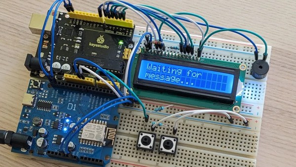
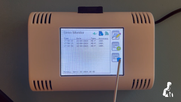
OK, let’s face it — even with objective proof there’s likely nothing that [Christopher Cooper] is going to do about the new crop of sirens going off in his neighborhood. Emergencies require a speedy response, after all, and sirens are perhaps just the price that we pay to live close to each other. That doesn’t mean there’s no reason to monitor the neighborhood noise, though, so [Christopher] got to work. The system uses an Arduino BLE Sense module to detect neighborhood noises and Edge Impulse to classify the sounds. An ESP32 does most of the heavy lifting, including running the UI on a nice little TFT touchscreen.
When a siren-like sound is detected, the sensor records the event and tries to classify the type of siren — fire, police, or ambulance. You can also manually classify sounds the system fails to understand, and export a summary of events to an SD card. If your neighborhood noise problems tend more to barking dogs or early-morning leaf blowers, no problem — you can easily train different models.
While we can’t say that this will help keep the peace in his neighborhood, we really like the way this one came out. We’ve seen the BLE Sense and Edge Impulse team up before, too, for everything from tuning a bike suspension to calming a nervous dog. Continue reading “AI System Drops A Dime On Noisy Neighbors”