Watch Life Tick Away, One LED Segment At A Time

In the grand scheme of things, a single human lifetime is a drop in the bucket. Even if we don’t like to acknowledge it, we all know the meter is running so to speak. Yet you’re still squandering your precious time on this Earth by reading Hackaday instead of doing something constructive. Of course nobody is burning up more time on this site than those of us who are writing it all, so don’t feel too bad.

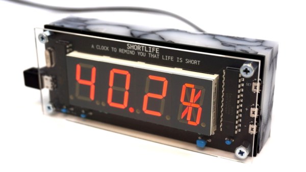
To remind us that life is fleeting, [Dries Depoorter] has designed the Shortlife: a device that counts down until your expected departure date. Before you get too excited, it can’t predict the future. The gadget is programmed with the vital statistics for the individual user, and data provided by the World Health Organization is used to calculate how much of your estimated life expectancy has already elapsed. Some would find this information depressing, while others will no doubt look at it as a source of inspiration. Us? We just think its a slick piece of gear.

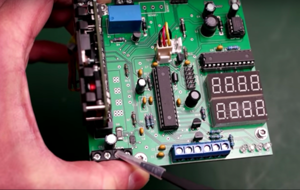
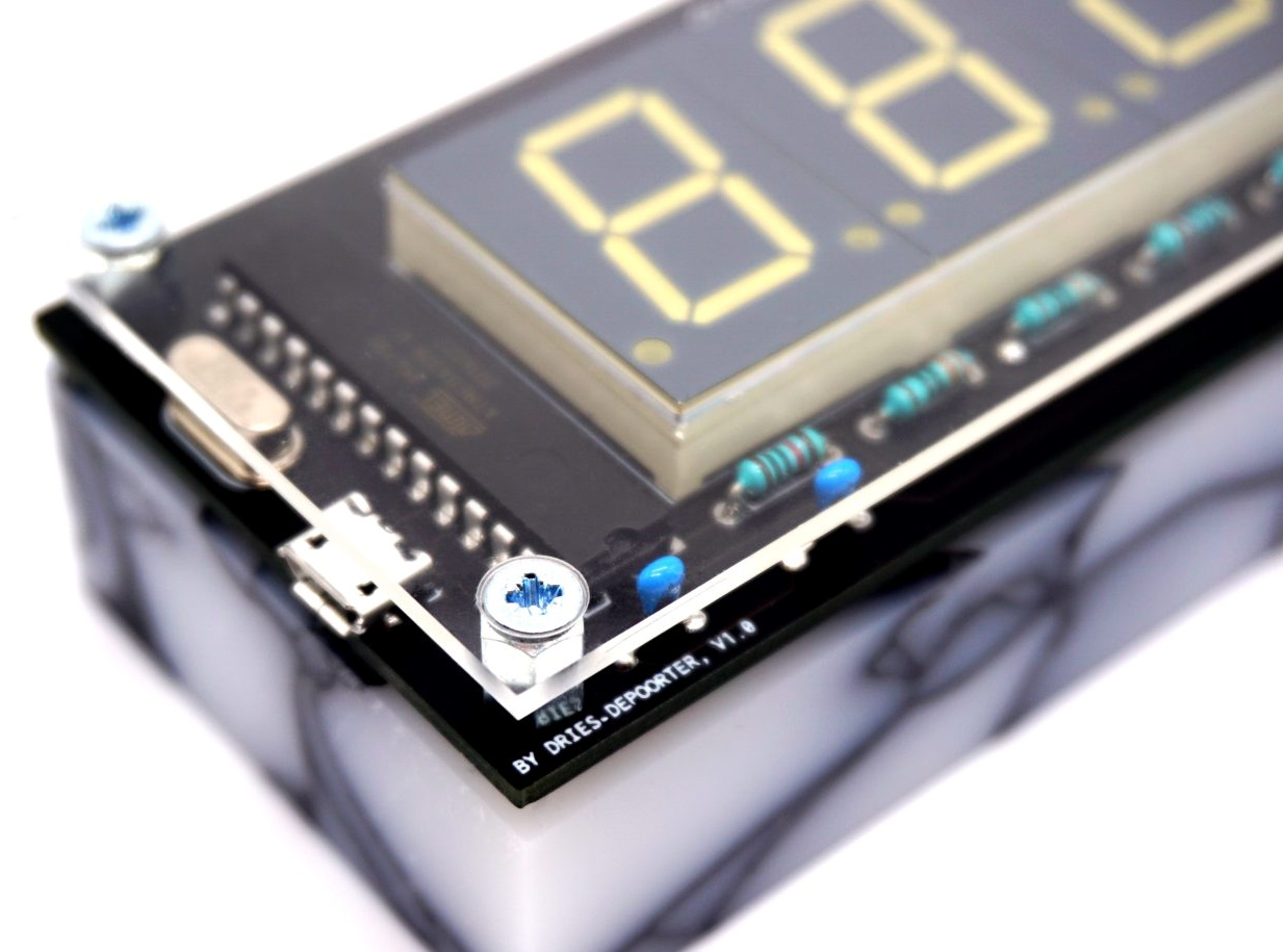
The Shortlife is made up of a custom PCB mounted to a marbled block of recycled plastic. On the board there’s an ATmega328 microcontroller, a MAX7219 LED driver, and of course the red LED segment displays. Three of them are the classic seven count, while the rightmost display sports fourteen segments for a bit of added accuracy. All the user has to do if they want to watch their remaining time slip away is plug the device into a USB power source and set the current time.

We’ve seen similar mortal countdown clocks in the past, but the Shortlife certainly brings a certain level of elegance to the idea. Plus we also like the fact that you’re just a line of code or two away from having the display tick down to some other date in the future when that whole existential crisis kicks in

Probability-Based Drummer Leaves The Beats Up To Chance

Drum machines may seem like one of the many rites of passage for hardware makers, they’re a concept you can implement simply or take into the extreme making it as complex as you want. [Matt’s] DrumKid is one of them, and its long development history is wonderfully documented in the project logs.

[Matt’s] original intention was to use the automatic drummer as part of his band, wanting “the expressiveness of a good drummer but without the robotic tendencies of a simple drum machine”. For that, he created the first iteration of the DrumKid, a web-based project using the Web Audio API. The interface consisted of bars showing levels for different settings which could be intuitively tweaked, changing the probability of a drum sound being played. This gave the “drummer” its unpredictability, setting itself apart from any regular old drum machine.

Fast forward a few years, and [Matt] now wants to recreate his DrumKid as a proper piece of musical gear, porting the concept into a standalone hardware drum machine you can plug into your mixer. He decided to go with the Arduino framework for his project rather than the Teensy platform in order to make it cheaper to build. The controls are simplified down to a few buttons and potentiometers, and the whole thing runs off of three AAA batteries. Also, targeting the project for hardware like this allowed for new features to be added, such as a bit-crush filter.

We already saw the first prototype here on Hackaday when it was featured in a Hackaday Prize mentor session, and it’s nice to see how the project evolved since. After a number of revisions, the new prototype takes design cues from Teenage Engineering’s “Pocket Operator” drum machine, using the main PCB as its own faceplate rather than a 3D printed case in a familiar way we’ve seen before. Unfortunately, the latest board is non-functional due to a routing mistake, but you can see the previous working prototypes in his project logs.

Better Than Original Pong Using Arduino

Games like Pong are legendary, not only in the sense that they are classic hours fun but also that they have a great potential for makers in stretching their learning legs. In an attempt at recreating the original paddle games like Pong and Tennis etc, [Grant Searle] has gone into the depths of emulating the AY-2-8500 chip using an Arduino.

For the uninitiated, the AY-3-8500 chip was the original game silicon that powered Ball & Paddle that could be played on the domestic television. Running at 2 MHz, it presented a 500 ns pixel width and operated to a maximum of 12 Volts. The equivalent of the AY-3-8500 is the TMS1965NLA manufactured by Texas Instruments for those who would be interested.

[Grant Searle] does a brilliant job of going into the details of the original chip as well as the PAL and NTSC versions of the device. This analysis will come in handy should anyone choose to make a better version. He talks about the intricacies of redrawing the screen for the static elements as well as the ball that bounces around the screen. The author presents details on ball traversal, resolution, 2K memory limit and its workarounds.

Then there are details on the sound and the breadboard version of the prototype that makes the whole write-up worth one’s time. If you don’t fancy the analog paddles and would rather use a wireless modern-day touch, check out Playing Pong with Micro:bits

Thanks [Keith O] for the tip.

Smart Outlet Cover Offers Lessons On Going From Project To Product

Going from idea to one-off widget is one thing; engineering the widget into a marketable product is quite another. So sometimes it’s instructive to take an in-depth look at a project that was designed from the get-go to be a consumer product, like this power indicating wall outlet cover plate. The fact that it’s a pretty cool project helps too.

Although [Vitaliy] has been working on this project for a while, he only recently tipped us off to it, and we’re glad he did because there’s a lot to learn here. His goal was to build a replacement cover for a standard North American power outlet that indicates how much power is being used by whatever is plugged into it. He set constraints that included having everything fit into the familiar outlet cover form factor, as well as to not require any modification to the existing outlet or rewiring, so that a consumer can just remove the old cover and put on the new one. Given the extremely limited space inside an outlet cover, these were significant challenges, but [Vitaliy] found a way. Current is sensed with two inductors positioned to sense magnetic flux within the outlet, amplified by a differential amp, and power use is calculated by an ATmega328 for display on 10 LEDs. Power for the electronics is tapped right from the outlet wiring terminals by spring clips, and everything fits neatly inside the cover.

It’s a great design, but not without issues. We look forward to seeing [Vitaliy] tackle those problems and bring this to market. For more on what it takes to turn a project into a product, check out our own [Lewin Day]’s story of bringing a guitar effects pedal to market.

Continue reading “Smart Outlet Cover Offers Lessons On Going From Project To Product”

Hacking A 30-year-old Russian VFD

Reddit user [InThePartsBin] found some VFDs (Vacuum Fluorescent Displays) on an old PCB on eBay. The Russian boards date from 1987 and have a bunch of through-hole resistors, transistors and a some mystery ICs, plastic wraps around the legs and the top of the tube is held steady by a rubber grommet (the tip itself goes through a hole in a board mounted perpendicular to the main board.) Being the curious kind of person we like, and seeing the boards weren’t too expensive, he bought some in order to play around with to see if he could bring them back to life.

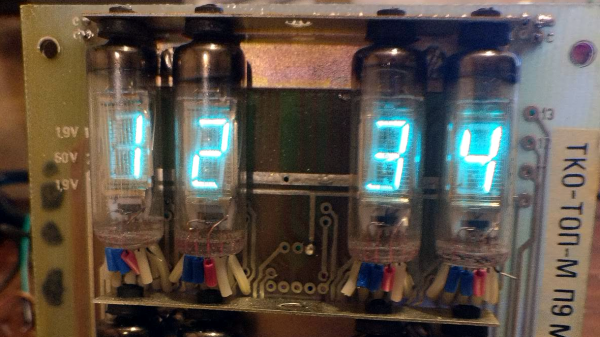
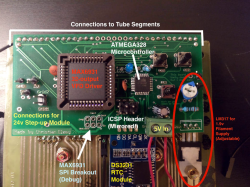
After getting the VFDs lighting up and figuring out the circuitry on the back, [InThePartsBin] decided that a clock was the best thing to build out of it. It was decided that a specialized VFD driver chip was the easiest way to make the thing work, so a MAX6934 was ordered. To give the clock some brains, an ATmega328 was recruited and to keep time, [InThePartsBin] had some DS3231 real-time clock modules left over from a previous project, so they were recruited as well. A daughterboard was designed to sit on the back of the vintage board and hold the ‘328 and the VFD driver chip.

Once [InThePartsBin] soldered on the components it was time to fire it up and send 1’s to the driver to turn on all the segments on all the tubes. Success! The only thing that [InThePartsBin] has left to do is write the code for the clock, but all the segments and tubes are controllable now, so the hardware part is done. There are other VFD clock projects on the site: Check out this one, or this one, and bask in the beautiful steel-blue glow.

Via Reddit.

Bench Power Supply Uses Server Voltage Regulator

If you stuff a computer into a rack with a bunch of other machines, you’d better make it a tough machine. Server-grade means something, so using server parts in a project, like this high-wattage power supply using server voltage regulators, can take it to the next level of robustness.

But before [Andy Brown] could build this power supply, he had to reverse-engineer the modules. Based on what he learned, and armed with a data sheet for the modules, he designed a controller to take advantage of all the capabilities of them and ended up with a full-featured power supply. The modules are rated for 66 watts total dissipation at 3.3 volts and have a secondary 5-volt output. Using an ATmega328, [Andy] was able to control the module, provide a display for voltage and current, temperature sensing and fan control, and even a UART to allow data logging to a serial port. His design features mainly through-hole components to make the build accessible to everyone. A suitable case is yet to come, and we’re looking forward to seeing the finished product.

Can’t scrape together some of these modules on eBay? Or perhaps you prefer linear power supplies to switched- mode? No worries – here’s a super stable unregulated supply for you.

Continue reading “Bench Power Supply Uses Server Voltage Regulator”