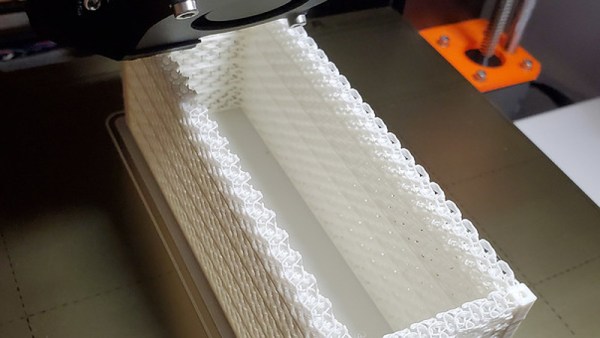
Desiccant is common in 3D printing because the drier plastic filament is, the better it prints. Beads of silica gel are great for controlling humidity, but finding a porous container for them that is a convenient size is a little harder. 3D printing is a generally useful solution for custom containers, but suffers from a slight drawback in this case: printing dense grills or hole patterns is not very efficient for filament-based printers. Dense hole patterns means lots of stopping and starting for the extruder, which means a lot of filament retractions and longer print times in general.
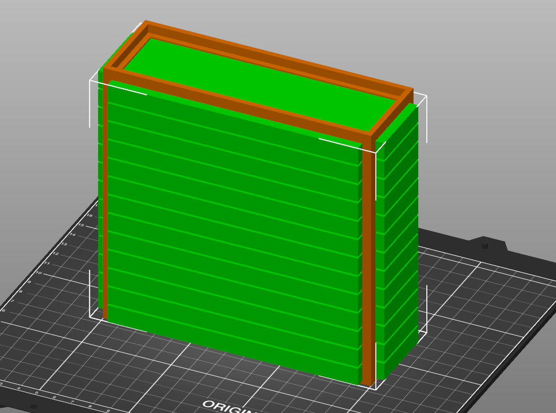
The green model is used as a modifier to the orange container (of which only the corners are left visible here)
[The_Redcoat]’s solution to this is to avoid hole patterns or grills altogether, and instead print large wall sections of the container as infill-only, with no perimeter layers at all. The exposed infill pattern is dense enough to prevent small beads of desiccant from falling through, while allowing ample airflow at the same time. The big advantage here is that infill patterns are also quite efficient for the printer to lay down. Instead of the loads of stops and starts and retractions needed to print a network of holes, infill patterns are mostly extruded in layers of unbroken lines. This translates to faster print speeds and an overall more reliable outcome, even on printers that might not be as well tuned or calibrated as they could be.
To get this result, [The_Redcoat] modeled a normal, flat-walled container then used OpenSCAD to create a stack of segments to use as a modifier in PrusaSlicer. The container is printed as normal, except where it intersects with the modifier, in which case those areas get printed with infill only and no walls. The result is what you see here: enough airflow for the desiccant to do its job, while not allowing any of the beads to escape. It’s a clever use of both a high infill as well as the ability to use a 3D model as a slicing modifier.
There’s also another approach to avoiding having to print a dense pattern of holes, though it is for light-duty applications only: embedding a material like tulle into a 3D print, for example, can make a pretty great fan filter.
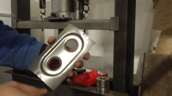
Press-forming is a versatile metal forming technique that can quickly and easily turn sheet metal into finished parts. But there’s a lot of time and money tied up in the tooling needed, which can make it hard for the home-gamer to get into. Unless you 3D-print your press-form tooling, of course.
Observant readers will no doubt recall our previous coverage of press-forming attempts with plastic tooling, which were met with varying degrees of success. But [Dave]’s effort stands apart for a number of reasons, not least of which is his relative newbishness when it comes to hot-squirt manufacturing. Even so, he still came up with an interesting gradient infill technique that put most of the plastic at the working face of the dies. That kept print times in the reasonable range, at least compared to the days of printing that would have been needed for 100% infill through the whole tool profile.
The other innovation that we liked was the idea to use epoxy resin to reinforce the tools. Filling the infill spaces on the tools’ undersides with resin resulted in a solid, strong block that was better able to withstand pressing forces. [Dave] didn’t fully account for the exothermic natures of the polymerization reaction, though, and slightly warped the tools. But as the video below shows, even suboptimal tools can perform, bending everything he threw at them, including the hydraulic press to some extent.
It sure seems like this is one technique to keep in mind for a rainy day. And hats off to [Dave] for sharing what didn’t work, since it points the way to improvements.
There’s a lot of folklore around post-processing of prints from FDM printers. Proponents swear by their methods, which are generally intended to either strengthen the part or to improve its appearance, or both. But do they actually work?
Knowing that a collection of anecdotes is no substitute for actual data, [Stefan] from CNC Kitchen has again performed some valuable experiments, this time testing the strength of parts that have been annealed in salt. This was a follow-up to his recent experiments with baking prints after entombing them in plaster, which yielded mixed results in terms of strength gains. Viewers commented that common salt makes a good medium for annealing prints, so he set about finding the right kind of salt. It turns out that the finer the grain, the better — powdery salt packs tighter and leaves little space for the softened plastic to flow — but that powdery salt is not easier to find. He ended up making his own by pulverizing table salt in a blender. He also had to play around with temperatures and times until coming up with a good process.
The results are impressive. PETG, ABS, and two varieties of PLA prints tested with force applied perpendicular to the print layers all showed marked increase in strength after breaking, to the point of nearly matching the strength of parts printed with the layers parallel to the stress. As with the plaster, parts were printed at 100% infill; a Benchy printed at 20% was notably unseaworthy after annealing. Surface finish on the annealed parts is an interesting combination of pitting with white residue — not unattractive but still a bit weird.
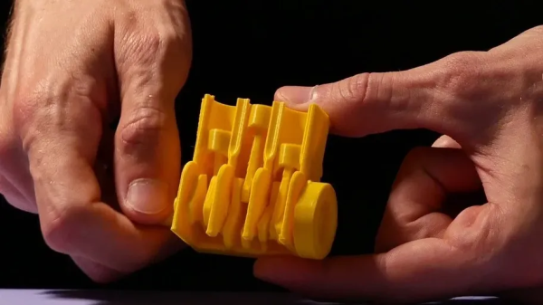
While there are many in the 3D-printing community who loudly and proudly proclaim never to have stooped to printing a 3DBenchy, there are far more who have turned a new printer loose on the venerable test model, just to see what it can do. But Benchy is getting a little long in the tooth, and with 3D-printers getting better and better, perhaps a better benchmarking model is in order.
Knocking Benchy off its perch is the idea behind this print-in-place engine benchmark, at least according to [SunShine]. And we have to say that he’s come up with an impressive model. It’s a cutaway of a three-cylinder reciprocating engine, complete with crankshaft, connecting rods, pistons, and engine block. It’s designed to print all in one go, with only a little cleanup needed after printing before the model is ready to go. The print-in-place aspect seems to be the main test of a printer — if you can get this engine to actually spin, you’re probably set up pretty well. [SunShine] shares a few tips to get your printer dialed in, and shows a few examples of what can happen when things go wrong. In addition to the complexities of the print-in-place mechanism, the model has a few Easter eggs to really challenge your printer, like the tiny oil channel running the length of the crankshaft.
Whether this model supplants Benchy is up for debate, but even if it doesn’t, it’s still a cool design that would be fun to play with. Either way, as [SunShine] points out, you’ll need a really flat bed to print this one; luckily, he recently came up with a compliant mechanism dial indicator to help with that job.
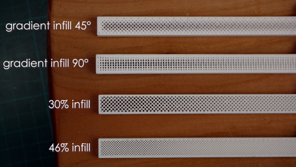
It is always tricky setting the infill for a 3D printed part. High infill parts are strong but take longer to print, while low infill prints take less time, but are weaker internally and in danger of surface layer droop between the infill pattern. [Stephan] has a better answer: gradient infill. You can see a video below and find his Python code on GitHub.
The idea is simple enough. In most cases, parts under stress see higher stress near the surface. Putting more material there will make the part stronger than adding plastic in places where the stress is lower. [Stephan] has done finite element analysis to determine an optimal infill pattern before, but this is somewhat difficult to do. Since the majority of parts can follow the more at the edges and less at the center rule, gradient infill makes sense except for a few special cases.
Generally speaking, objects made on desktop 3D printers are pretty small. This is of course no surprise, as filament based printers are fairly slow and most don’t have very large beds to begin with. Most people don’t want to wait days for their project to complete, so they use 3D printed parts where it makes sense and supplement them with more traditional components such as aluminum extrusion wherever possible. But not always…
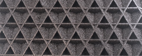
This 3D printed photography softbox created by [Nicholas Sherlock] doesn’t take the easy way out for anything. With the exception of the LEDs and the electronics to drive them, everything in the design has been printed on his Prusa i3. It wasn’t the easiest or fastest way to do it, but it’s hard to argue with the end result. Perhaps even more impressive than the final product is what it took to get there: he actually had to develop a completely new style of part infill he’s calling “Scattered Rectilinear” to pull it off.
Overall the design of the light itself isn’t that complex, ultimately it’s just a box with some LEDs mounted at the back and a pretty simple circuit to control their intensity. The critics will say he could have just used a cardboard box, or maybe wood if he wanted something a little bit stronger. But the point of this project was never the box itself, or the LEDs inside it. It’s all about the diffuser.
[Nicholas] forked Prusa’s version of Slic3r to add in his “Scattered Rectilinear” infill pattern, which is specifically designed to avoid the standard “ribs” inside of a 3D printed object. This is accomplished with randomized straight infill passes, rather than the traditionally overlapped ones. The inside of the print looks very reminiscent of fiberglass mat, which is perhaps the best way to conceptualize its construction. In terms of the final part strength, this infill is abysmal. But on the plus side, the light from the LEDs passing through it emerges with a soft pleasing look that completely obscures the individual points of light.
Anyone with a big enough 3D printer can run off their own copy of his light, as [Nicholas] has released not only his forked version of Slic3r but all of the STL files for the individual components. He’s also put together an exceptionally well documented Thingiverse page that has instructions and detailed build photos, something that’s unfortunately very rare for that platform.
Makerbot is in the gutter, 3D Systems and Stratasys stock is only a shadow of their 2014 glory, but this is the best year 3D printing has ever had. Machines are now good and cheap, there’s a variety of various thermoplastic filaments, and printing useful objects – instead of just plastic trinkets – is becoming commonplace.
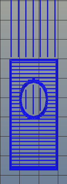
The standard rectilinear infill from Slic3r
There’s one area of 3D printing that hasn’t seen as much progress, and it’s the software stack. Slicing, the process of turning a 3D object into a Gcode file for a printer has been basically the same for the last few years. Dual extrusion is still a mess, and automated bed leveling is still in its infancy.
One aspect of slicing that has been severely overlooked is infill. Obviously, you don’t want to print plastic trinkets completely solid – only the outside surface matters, and a part with 100% infill is just a waste of plastic. Different slicers have come up with different ways of filling the inside of a print, usually with a grid of squares, triangles, or hexagons.
While the most popular methods of filling in a 3D printed objects do the job of adding a little bit of strength to a print and supporting the top layers of a print, it’s not an ideal solution. The desired strength of the finished part is never taken into account, print artifacts are sometimes visible through the side of a print, and the spacing of the infill grid is completely arbitrary. You can only set a percentage of infill, and telling a slicer to make an internal support grid with 10mm spacing is impossible.
Type A Machines just changed all of this. With the release of their public beta of Cura Type A, the infill for a 3D printed part is also 3D. The dimensions of the infill are predictable, opening the door to stronger and better looking parts.
From the Type A press literature and white paper, this new type of ‘infill’ isn’t; it’s more properly referred to as ‘internal structure’, with proper dimensions between infill features. Instead of a grid of squares or triangles stacked one layer on top of each other, it’s a true structure, with the infill following the perimeter of the 3D printed object.
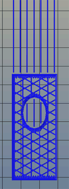
Generating 3D Infill
Infill generated from Type A Machine’s Cura beta. Note the 3D structure of the infill.
Right now, infill is generated in a slicer by specifying a percentage. Zero percent infill means a hollow object, and 100% infill is a completely solid part. These two edge cases are easy, but anything else means the slicer must fill the part with filament in a grid of tessellating shapes, either rectangles, triangles, or hexagons. With current slicers, the dimensions of this internal structure are, for all practical purposes, random. Printing an object with 20% infill might mean a grid of squares with 5mm or 2mm spacing. Telling the slicer to infill a part with a grid of squares spaced 10mm apart is impossible.
Type A Machine’s latest Cura release changes all of this, allowing a designer to set a precise distance between rows and columns of infill. By defining infill in absolute dimensions, this allows for stronger parts using less infill.
Absolute dimensioning is only one feature of the Type A Machine’s latest release of Cura. Even more exciting is the development of 3D internal structure. Instead of stacking layers of squares, triangles, or hexagons on top of each other, Type A Machine’s Cura uses an infill of cubes turned on their side. While each individual layer of infill looks like a series of triangles and irregular hexagons, when assembled into a printed 3D object, this infill forms a true 3D structure.
The closest comparison to this sort of structure is the difference between graphite and diamond. Both of these materials are made out of the same element, carbon. The physical structure of graphite is just, 1-atom-thick layers of graphene, producing a relatively weak material. Diamond, on the other hand, has a true 3D structure and is one of the hardest materials known to man. While adding 3D structure to the infill of 3D printed objects won’t make the objects any stronger, it will drastically reduce delamination, and be much more resistant to stresses in all three dimensions.
While Type A Machines has done some great work here, it does mean there’s yet another version of Cura to deal with. Type A Machine’s Cura, in addition to the LulzBot edition and the original are now the defacto standard for turning 3D objects into printed parts. Having an open source solution is great, but forking the development this much surely can’t be ideal.