Junk Bin Cyberdish Turns You Into The Satellite Tracker

The good thing about listening in on satellites is that they tend to beam down all kinds of juicy information from their lofty perches. The bad thing about satellites is that to stay in those orbits, they’ve got to be moving really fast, and that means that you’ve got to track them if you want to keep a nice consistent signal during a pass. And that can lead to all sorts of complexity, with motorized two-axis mounts and fancy tracking software.

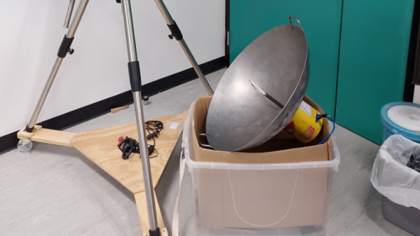
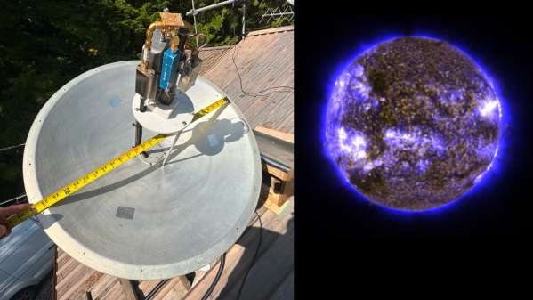
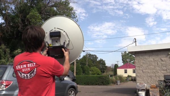
Or does it? Not if you’re willing to act as the antenna mount, which is the boat [Gabe] from the saveitforparts channel on YouTube recently found himself in when searching for L-band signals from the GOES satellite. His GOES setup uses a 30″ (0.8 m) dish repurposed from a long-range wireless networking rig. Unfortunately, the old security camera pan-tilt unit it was mounted on wasn’t quite up to satellite tracking duty, so [Gabe] pulled the dish off and converted it to manual tracking.

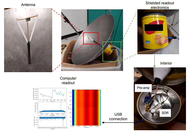
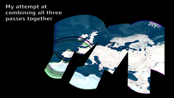
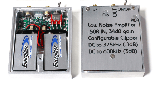
With a freshly wound helical antenna and a SAWbird LNA at the focal point, the dish proved to be pretty easy to keep on track manually, while providing quite the isometric workout. Aiming was aided by an app called Stellarium which uses augmented reality to point out objects in the night sky, and a cheap tablet computer was tasked with running SDR++ and capturing data. Sadly, neither of these additions brought much to the party, with the latter quickly breaking and the former geared more toward stargazing than satellite snooping. But with some patience — and some upper-body strength — [Gabe] was able to track GOES well enough with the all-in-one “cyberdish” to get some usable images. The whole saga is documented in the video after the break.

Kudos to [Gabe] for showing us what can be accomplished with a little bit of junk and a lot of sticktoitiveness. He promises that a legit two-axis mount is in the works, so we’ll be on the lookout for that. We’ve seen a few of those before, and [Chris Lott] did a great overview of satellite tracking gear a while back, too.

Continue reading “Junk Bin Cyberdish Turns You Into The Satellite Tracker”

Wok Your Way To The Center Of The Galaxy

The round bottom of a proper wok is the key to a decent stir fry, but it also makes it hard to use on traditional Western stoves. That’s why many woks end up in a dark kitchen cabinet, unused and unloved. But wait; it turns out that the round bottom of a wok is the perfect shape for gathering something else — radio waves, specifically the 21-cm neutral hydrogen emissions coming from the heart of our galaxy.

Turning a wok into an entry-level radio telescope doesn’t appear to be all that hard, at least judging by what [Leo W.H. Fung] et al detail in their paper (PDF) on “WTH” or “Wok the Hydrogen.” Aside from the wok, which serves as the main reflector, you’ll need a bit of coaxial cable and some stiff copper wire to fashion a small dipole antenna and balun, plus some plastic tubing to support it at the focal point of the reflector. Measuring the wok’s shape and size, which in turn determines its focal point, is probably the hardest part of the build; luckily, the paper includes tips on doing just that. The authors address the controversy of parabolic versus spherical reflectors and arrive at the conclusion that for a radio telescope fashioned from a wok, it just doesn’t matter.

As for the signal processing chain, WTH holds few surprises. A Nooelec Sawbird+ H1 acts as preamp and filter for the 1420-MHz hydrogen line signal, which feeds into an RTL-SDR dongle. Careful attention is paid to proper grounding and shielding to keep the noise floor as low as possible. Mounting the antenna is a decidedly ad hoc affair, and aiming is as simple as eyeballing various stars near the center of the galactic plane — no need to complicate things.

Performance is pretty good: WTH measured the recession velocity of neutral hydrogen to within 20 km/s, which isn’t bad for something cobbled together from scrap. We’ve seen plenty of DIY hydrogen line observatories before, but WTH probably wins the “get on the air tonight” award.

Thanks to [Heinz-Bernd Eggenstein] for the tip.

Listening In On A Deep-Space Satellite As It Returns Home

We’ve covered dozens of projects about getting images of Earth’s weather straight from the source. It’s not too much of a trick to download images straight from our constellation of weather satellites, but what about space weather? We’ve got satellites for that too, of course, but to get a good look at the Sun, they’re out of reach of most homebrew ground stations.

That’s about to change, though, as STEREO-A returns to our neighborhood after a 17-year absence, making citizen science a reasonable proposition. The STEREO mission — Solar Terrestrial Relations Observatory — was launched in 2006 with a pair of satellites in heliocentric orbits. STEREO-B was lost in 2014 due to a navigational glitch, but STEREO-A has spent a lot of the intervening years watching the backside of the Sun relative to the Earth. As [Scott Tilley] explains, the satellite is now approaching inferior conjunction, where it will pass between the Earth and the Sun.

This close pass makes STEREO-A’s X-band deep-space beacon readily available to hobbyist-scale equipment, like [Scott]’s 66-cm dish antenna. The dish is mounted on an alt-az telescope mount for tracking, and sports a host of gear at the focus, like LNAs, filters, mixers, and an Ettus B200 SDR. It’s not a cheap setup, but compared to what’s usually needed to listen to STEREO-A, it’s a bargain. The process of demodulating and decoding the signals was a bit more involved, though, requiring not only SatDump and some custom code but also a lot of patience. The images are worth the wait, though; [Scott] shares some amazing shots of our increasingly active Sun as well as animations of recent sunspot activity.

If you’re interested in getting in on the STEREO-A action, you’d better get hopping — the satellite will only be in the neighborhood for a few more months before heading off for another pass around the back of the Sun.

Using An Old Satellite To See The Earth In A New Light

Snooping in on satellites is getting to be quite popular, enough so that the number of people advancing the state of the art — not to mention the wealth of satellites transmitting signals in the clear — has almost made the hobby too easy. An SDR, a homebrew antenna, and some off-the-shelf software, and you too can see weather satellite images on your screen in real time.

But where’s the challenge? That seems to be the question [dereksgc] asked and answered by tapping into S-band telemetry from an obsolete satellite. Most satellite hunters focus on downlinks in the L-band or even the VHF portion of the spectrum, which are within easy reach of most RTL-SDR dongles. However, the Coriolis satellite, which was launched in 2003, has a downlink firmly in the S-band, which at 2.2-GHz puts it just outside the high end of an RTL-SDR. To work around this, [dereksgc] bought a knock-off HackRF SDR and couple it with a wideband low-noise amplifier (LNA) of his own design. The dish antenna is also homebrewed from a used 1.8-m dish and a custom helical antenna for the right-hand circular polarized downlink signal.

As the video below shows, receiving downlink signals from Coriolis with the rig wasn’t all that difficult. Even with manually steering the dish, [dereksgc] was able to record a couple of decent passes with SDR#. Making sense of the data from WINDSAT, a passive microwave polarimetric radiometer that’s the main instrument that’s still working on the satellite, was another matter. Decoded with SatDump and massaged with Gimp, the microwave images of Europe are at least recognizable, mostly due to Italy’s distinctive shape.

Despite the distortion, seeing the planet’s surface via the microwaves emitted by water vapor is still pretty cool. If more traditional weather satellite images are what you’re looking for, those are pretty cool too.

Continue reading “Using An Old Satellite To See The Earth In A New Light”

An aluminium case with a small PCB and two nine-volt batteries inside

A Low-Noise Amplifier To Quantify Resistor Noise

Noise is all around us, and while acoustic noise is easy to spot using our ears, electronic noise is far harder to quantify even with the right instruments. A spectrum analyzer is the most convenient tool for noise measurements, but also adds noise of its own to whatever signal you’re looking at. [Limpkin] has been working on measuring very small noise signals using a spectrum analyzer, and shared his results in a comprehensive blog post.

The target he set himself was to measure the noise produced by a 50 Ohm resistor, which is the impedance most commonly seen on the inputs and outputs of RF systems. The formula for Johnson-Nyquist noise power tells us that the expected noise voltage in a one-hertz bandwidth is just 0.9 nanovolts – tiny by any standard, and an order of magnitude smaller than the noise floor of a typical spectrum analyzer. [Limpkin] therefore designed an amplifier and signal buffer to crank up the noise signal by a factor of 100, using ultra-low noise op amps running off a pair of nine-volt batteries.

There was a problem with this circuit, however: any stray DC voltage present at its input would also be amplified to levels that could damage the analyzer’s sensitive input port. To prevent this, [Limpkin] decided to add a clipper circuit to his amplifier. This consists of a pair of comparators that continuously monitor the amplifier’s output voltage and disconnect it through a silicon switch if it goes beyond 200 millivolts. [Limpkin] packaged his circuit in a beautifully-machined case and ran various tests to ensure the clipper worked reliably even in the presence of fast input transients.

With the clipper in place, it was safe to run the planned noise measurements. The end result? About 0.89 nV, just as predicted by theory. Measuring nanovolt-level signals usually requires extremely accurate equipment and lots of tricks to minimize noise. Sometimes though, noise is just what you need to make a radio transmitter. Thanks for the tip, [alfonso32]!

A Single-Resistor Radio Transmitter, Thanks To The Power Of Noise

One of the great things about the Hackaday community is how quickly you find out what you don’t know. That’s not a bad thing, of course; after all, everyone is here to get smarter, right? So let’s work together to get our heads around this paper (PDF) by [Zerina Kapetanovic], [Miguel Morales], and [Joshua R. Smith] from the University of Washington, which purports to construct a low-throughput RF transmitter from little more than a resistor.

This witchcraft is made possible thanks to Johnson noise, also known as Johnson-Nyquist noise, which is the white noise generated by charge carriers in a conductor. In effect, the movement of electrons in a material thanks to thermal energy produces noise across the spectrum. Reducing interference from Johnson noise is why telescopes often have their sensors cooled to cryogenic temperatures. Rather than trying to eliminate Johnson noise, these experiments use it to build an RF transmitter, and with easily available and relatively cheap equipment. Continue reading “A Single-Resistor Radio Transmitter, Thanks To The Power Of Noise”

Take A Deep Dive Into A Commodity Automotive Radar Chip

When the automobile industry really began to take off in the 1930s, radar was barely in its infancy, and there was no reason to think something that complicated would ever make its way into the typical car. Yet here we stand less than 100 years later, and radar has been perfected and streamlined so much that an entire radar set can be built on a single chip, and commodity radar modules can be sprinkled all around the average vehicle.

Looking inside these modules is always fascinating, especially when your tour guide is [Shahriar Shahramian] of The Signal Path, as it is for this deep dive into an Infineon 24-GHz automotive radar module. The interesting bit here is the BGT24LTR11 Doppler radar ASIC that Infineon uses in the module, because, well, there’s really not much else on the board. The degree of integration is astonishing here, and [Shahriar]’s walk-through of the datasheet is excellent, as always.

Things get interesting once he gets the module under the microscope and into the X-ray machine, but really interesting once the RF ASIC is uncapped, at the 15:18 mark. The die shots of the silicon germanium chip are impressively clear, and the analysis of all the main circuit blocks — voltage-controlled oscillator, power amps, mixer,  LNAs — is clear and understandable. For our money, though, the best part is the look at the VCO circuit, which appears to use a bank of fuses to tune the tank inductor and keep the radar within a tight 250-Mz bandwidth, for regulatory reasons. We’d love to know more about the process used in the factory to do that bit.

This isn’t [Shahriar]’s first foray into automotive radar, of course — he looked at a 77-GHz FMCW car radar a while back. That one was bizarrely complicated, though, so there’s something more approachable about a commodity product like this.

Continue reading “Take A Deep Dive Into A Commodity Automotive Radar Chip”