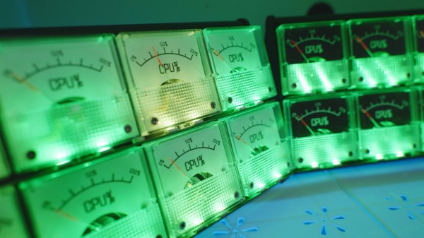
With the demands of modern computing, from video editing, streaming, and gaming, many of us will turn to a monitoring system of some point to keep tabs on CPU usage, temperatures, memory, and other physical states of our machines. Most are going to simply display on the screen but this data can be sent to external CPU monitors as well. This retro-styled monitor built on analog voltmeters does a great job of this and adds some flair to a modern workstation as well.
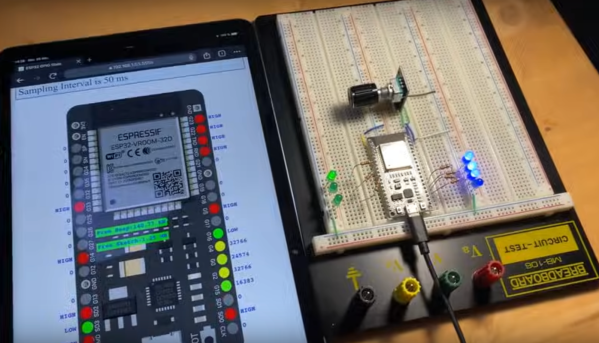
The build, known as bbMonitor, is based on the ESP32 platform which controls an array of voltmeters via PWM. The voltmeters have been modified with a percentage display to show things like CPU use percentage. Software running on the computers sends this data in real time to the ESP32 so the computer’s behavior can be viewed at a glance. Each voltmeter is also augmented with RGB LEDs that change color from green to red as use increases as well. The project’s creator, [Corebb], also notes that the gauges will bounce around if the computer is under heavy load but act more linearly when under constant load, also helping to keep an eye on computer status.
While the build does seem to rely on a Windows machine to run the software for export to the monitor, all of the code is open-sourced and available on the project’s GitHub page and could potentially be adapted for other operating systems. And, as far as the voltmeters themselves go, there have been similar projects in the past that use stepper motors as a CPU usage monitor instead.
Continue reading “Keep Tabs On PC Use With Custom Analog Voltmeter”