Future Brings CPU Modules, And The Future Is Now

Modularity is a fun topic for us. There’s something satisfying about seeing a complex system split into parts and these parts made replaceable. We often want some parts of our devices swapped, after all – for repair or upgrade purposes, and often, it’s just fun to scour eBay for laptop parts, equipping your Thinkpad with the combination of parts that fits you best. Having always been fascinated by modularity, I believe that hackers deserve to know what’s been happening on the CPU module front over the past decade.

A Youtube thumbnail showing a Thinpad in the background with "Not Garbage" written over its keyboard, and one more keyboard overlaid onto the picture with "garbage" written on that one.
This “swap your Thinkpad keyboard” video thumbnail captures a modularity-enabled sentiment many can relate to.

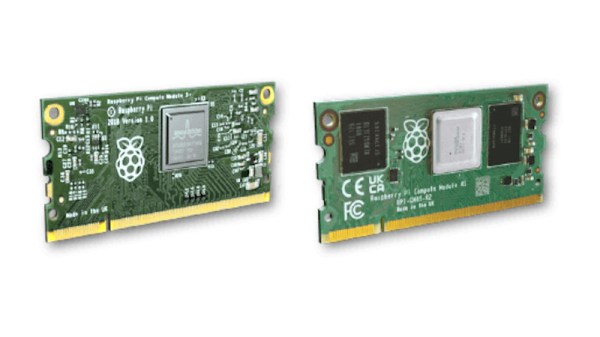
We’ve gotten used to swapping components in desktop PCs, given their unparalleled modularity, and it’s big news when someone tries to split a yet-monolithic concept like a phone or a laptop into modules. Sometimes, the CPU itself is put into a module. From the grandiose idea of Project Ara, to Intel’s Compute Card, to Framework laptop’s standardized motherboards, companies have been trying to capitalize on what CPU module standardization can bring them.

There’s some hobbyist-driven and hobbyist-friendly modular standards, too – the kind you can already use to wrangle a powerful layout-demanding CPU and RAM combo and place it on your simple self-designed board. I’d like to tell you about a few notable modular CPU concepts – their ideas, complexities, constraints and stories. As you work on that one ambitious project of yours – you know, the one, – it’s likely you will benefit a lot from such a standard. Or, perhaps, you’ll find it necessary to design the next standard for others to use – after all, we all know there’s never too few standards! Continue reading “Future Brings CPU Modules, And The Future Is Now”

Motherboard on the desk, with a CM4 plugged into it, and all kinds of wires connected to it for purposes of debugging

Hackaday Prize 2022: A CM4 Upgrade For Your Old IPad

There’s no shortage of nicely built tablets out there, but unfortunately many of them are powered by what are by now severely outdated motherboards. Since manufacturers releasing replacement motherboards for their old hardware doesn’t look like its likely to be common practice anytime soon, the community will have to take things into their own hands. This is where [Evan]’s project comes in — designing a Raspberry Pi CM4-powered motherboard for the original iPad. It aims to have support for everything you’d expect: display, touchscreen, audio, WiFi, Bluetooth, and even the dock port. Plus it gives you way more computing power to make use of it all.

Testing part fitment with some cardboard CAD.

The original iPad got a lot of things right, a factor definitely contributing to its success back when it was released. [Evan]’s high-effort retrofit works with the iPad’s plentiful good parts, like its solid shell, tailored lithium-ion battery, eye-friendly LCD, and reliable capacitive touchscreen. You’d have to fit the new motherboard inside the space available after these parts all come together, and [Evan] has shaped his PCBs to do exactly that – with room for CM4, and the numerous ICs he’s added so as to leave no function un-implemented.

This project has been underway for over a year, and currently, there’s fourteen information-dense worklogs telling this retrofit’s story. Reverse-engineering the capacitive touchscreen and the LCD, making breakouts for all the custom connectors, integrating a custom audio codec, debugging device tree problems, unconventional ways to access QFN pins left unconnected on accident, and the extensive power management design journey. [Evan] has a lot to teach for anyone looking to bring their old tablet up to date!

The hardware files are open-source, paving the way for others to reuse parts for their own retrofits, and we absolutely would like to see more rebuilds like this one. This project is part of the Hack it Back round of the 2022 Hackaday Prize, and looks like a perfect fit to us. If you were looking for an excuse to start a similar project, now is the time.

Sketch of the two proprietary carriers showing their differences - one of them has a cutout under the antenna, while the other one does not.

Design Your CM4 Carrier With WiFi Performance In Mind

The Raspberry Pi Compute Module 4 has a built-in WiFi antenna, but that doesn’t mean it will work well for you – the physical properties of the carrier board impact your signal quality, too. [Avian] decided to do a straightforward test – measuring WiFi RSSI changes and throughput with a few different carrier boards. It appears that the carriers he used were proprietary, but [Avian] provides sketches of how the CM4 is positioned on these.

There’s two recommendations for making WiFi work well on the CM4 – placing the module’s WiFi antenna at your carrier PCB’s edge, and adding a ground cutout of a specified size under the antenna. [Avian] made tests with three configurations in total – the CMIO4 official carrier board which adheres to both of these rules, carrier board A which adheres to neither, and carrier board B which seems to be a copy of board A with a ground cutout added.

Graph plotting WiFi RSSI for each of the three carriers in each of the six locations. CMIO4 consistently outperforms both, while carrier B outperforms the carrier A, but by a more narrow margin.
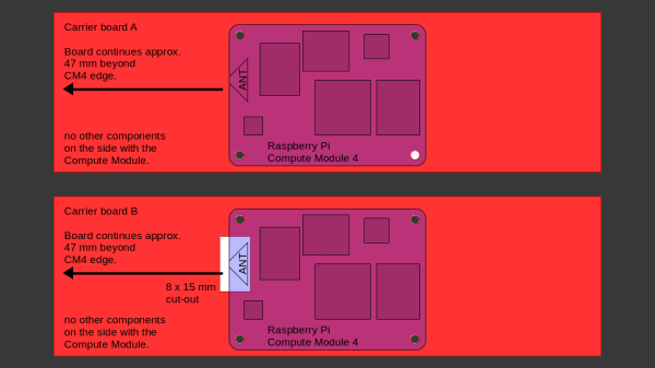
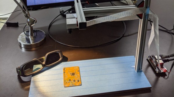
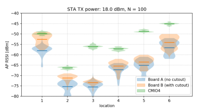
After setting up some test locations and writing a few scripts for ease of testing, [Avian] recorded the experiment data. Having that data plotted, it would seem that, while presence of an under-antenna cutout helps, it doesn’t affect RSSI as much as the module placement does. Of course, there’s way more variables that could affect RSSI results for your own designs – thankfully, the scripts used for logging are available, so you can test your own setups if need be.

If you’re lucky to be able to design with a CM4 in mind and an external antenna isn’t an option for you, this might help in squeezing out a bit more out of your WiFi antenna. [Avian]’s been testing things like these every now and then – a month ago, his ESP8266 GPIO 5V compatibility research led to us having a heated discussion on the topic yet again. It makes sense to stick to the design guidelines if WiFi’s critical for you – after all, even the HDMI interface on Raspberry Pi can make its own WiFi radio malfunction.

It’s Almost A New Raspberry Pi Compute Module 4. But Not Quite

We know that readers are familiar with the global chip shortage and its effects on product availability. The Raspberry Pi folks haven’t escaped its shadow, for even though they’ve managed to preserve availability of their RP2040 microcontroller, it’s fair to say that some of their flagship Linux-capable boards have been hard to find. All of this has had an unlikely effect in the form of a new Raspberry Pi, but unexpectedly it’s one which few end users are likely to get their hands on.

The Raspberry Pi Compute Module has been part of the range since the early days, and in its earlier versions took a SODIMM form factor. The last SODIMM Compute Module had a Pi 3 processor, and this unexpected new model is reported as having a very similar hardware specification but featuring the Pi 4 processor. It seems that the chip shortage has affected supplies of the earlier SoC, and to keep their many industrial customers for the SODIMM Compute Modules in business they’ve had to produce this upgrade. As yet it’s not surfaced for sale on its own and there’s a possibility it will stay only in the realm of industrial boards, but as the story develops there’s a Raspberry Pi forum topic about it for the latest and you can find the pertinent info in the video below the break.

Of course, the Compute Module of the moment remains the CM4 in its newer form factor, which we see as possibly the most exciting of all the Pi products of the moment. Meanwhile this is not the first custom industrial Raspberry Pi to be seen in the wild.

Continue reading “It’s Almost A New Raspberry Pi Compute Module 4. But Not Quite”

A pinout diagram of the new Pi 4, showing all the alternate interfaces available.

Did You Know That The Raspberry Pi 4 Has More SPI, I2C, UART Ports?

We’ve gotten used to the GPIO-available functions of Raspberry Pi computers remaining largely the same over the years, which is why it might have flown a little bit under the radar: the Raspberry Pi 4 has six SPI controllers, six I2C controllers, and six UARTs – all on its 40-pin header. You can’t make use of all of these at once, but with up to four different connections wired to a single pin you can carve out a pretty powerful combination of peripherals for your next robotics, automation or cat herding project.

The datasheet for these peripherals is pleasant to go through, with all the register maps nicely laid out – even if you don’t plan to work with the register mappings yourself, the maintainers of your preferred hardware enablement libraries will have an easier time! And, of course, these peripherals are present on the Compute Module 4, too. It might feel like such a deluge of interfaces is excessive, however, it lets you achieve some pretty cool stuff that wouldn’t be possible otherwise.

Having multiple I2C interfaces helps deal with various I2C-specific problems, such as address conflicts, throughput issues, and mixing devices that support different maximum speeds, which means you no longer need fancy mux chips to run five low-resolution Melexis thermal camera sensors at once. (Oh, and the I2C clock stretching bug has been fixed!) SPI interfaces are used for devices with high bandwidth, and with a few separate SPI ports, you could run multiple relatively high-resolution displays at once, No-Nixie Nixie clock style.

As for UARTs, the Raspberry Pi’s one-and-a-half UART interface has long been an issue in robotics and home automation applications. With a slew of devices like radio receivers/transmitters, LIDARs and resilient RS485 multi-drop interfaces available in UART form, it’s nice that you no longer have to sacrifice Bluetooth or a debug console to get some fancy sensors wired up to your robot’s brain. You can enable up to six UARTs. Continue reading “Did You Know That The Raspberry Pi 4 Has More SPI, I2C, UART Ports?”

magicBlueSmoke-piStick-featured

How Do You Make A Raspberry Pi On A Stick?

We agree with [magic-blue-smoke] that one of the only things more fun than a standard Raspberry Pi 4 is the Compute Module form factor. If they are not destined to be embedded in a system, these need a breakout board to be useful. Each can be customized with a myriad board shapes and ports, and that’s where the real fun starts. We’ve already seen projects that include custom carrier boards in everything from a 3D Printer to a NAS and one that shows we can build a single-sided board at home complete with high-speed ports.

[magic blue smoke] used this ability to customize the breakout board as an opportunity to create a hackable media player “stick” with the Raspberry Pi built-in. We love that this Raspberry Pi CM4 TV Stick eliminates all the adapters and cables usually required to connect a Pi’s fiddly micro HDMI ports to a display and has heat sinks and an IR receiver to boot. Like a consumer media player HDMI stick, all you need to add is power. Continue reading “How Do You Make A Raspberry Pi On A Stick?”

Raspberry Pi Cameras Stand In For Stereo Microscope

Handling tiny surface mount components and inspecting PCBs is a lot easier with a nice stereo microscope, but because of their cost and bulk, most hobbyists have to do without. At best they might have a basic digital microscope, but with only one camera, they can only show a 2D image that’s not ideal for detail work.

The team behind [Stereo Ninja] hopes to improve on the situation by developing a stereoscopic vision system that puts tiny objects up on the big screen in three dimensions. Utilizing the Raspberry Pi Compute Module, a custom carrier board that enables the use of both MIPI CSI camera interfaces, and a 3D gaming monitor, their creation combines the capabilities of a traditional stereo microscope with the flexibility of a digital solution.

With two Raspberry Pi cameras suspended over the work area, and the addition of plenty of LED light, Stereo Ninja is able to generate the 3D image required by the monitor. While the camera’s don’t have the same magnification you’d get from a microscope, they’re good enough for enlarging SMD parts, and looking at a big screen monitor certainly beats hunching over the eyepiece of a traditional microscope. Especially if you’re trying to show something to a group of people, like at a hackerspace.

Of course, not everyone has a large 3D gaming monitor on their workbench. In fact, given how poorly the tech went over with consumers the last time it was pushed on us, we’d wager more hackers have stereo microscopes than 3D displays. Which is why the team’s next step is to have the Raspberry Pi generate the signals required by the shutter glasses, allowing Stereo Ninja to show a three dimensional image on 2D monitors; bringing this valuable capability to far larger audience than has previously been possible.

Continue reading “Raspberry Pi Cameras Stand In For Stereo Microscope”