Retro Gadgets: The CB Cell Phone

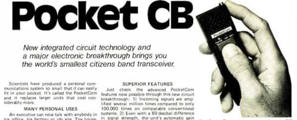
There was a time when one of the perks of having a ham radio in your car (or on your belt) was you could make phone calls using a “phone patch.” In the 1970s, calling someone from inside your parked car turned heads. Now, of course,  it is an everyday occurrence thanks to cell phones. But in 1977, cell phones were nowhere to be found. Joseph Sugarman, the well-known founder of JS&A, saw a need and wanted to fill it. So he offered the “PocketCom CB” which was billed as the “world’s smallest citizens band transceiver.” You can see the full-page ad from 1977 below.

Remember that this is from an era when ICs that could operate at 30 MHz were not the norm, so you have to temper your expectations. The little unit was 5.5 in by 1.5 in and less than an inch thick. That’s actually not bad, but you had — optimistically — 100 mW of output power. They claimed the N cell batteries would last two weeks with average use, but we imagine a lot less as soon as you start transmitting. The weight was 5 oz, but we suspect that is without the batteries.

Continue reading “Retro Gadgets: The CB Cell Phone”

How To Run A First-Generation Cell Phone Network

Retro tech is cool. Retro tech that works is even cooler. When we can see technology working, hold it in our hand, and use it as though we’ve been transported back in time; that’s when we feel truly connected to history. To help others create small time anomalies of their own, [Dmitrii Eliuseev] put together a quick how-to for creating your own Advanced Mobile Phone System (AMPS) network which can bring some of the classic cellular heroes of yesterday back to life.

Few readers will be surprised to learn that this project is built on software defined radio (SDR) and the Osmocom-Analog project, which we’ve seen before used to create a more modern GSM network at EMF Camp. Past projects were based on LimeSDR, but here we see that USRP is just as easily supported. [Dmitrii] also provides a brief history of AMPS, including some of the reasons it persisted so long, until 2007! The system features a very large coverage area with relatively few towers and has surprisingly good audio quality. He also discusses its disadvantages, primarily that anyone with a scanner and the right know-how could tune to the analog voice frequencies and eavesdrop on conversations. That alone, we must admit, is a pretty strong case for retiring the system.

The article does note that there may be legal issues with running your own cell network, so be sure to check your local regulations. He also points out that AMPS is robust enough to work short-range with a dummy load instead of an antenna, which may help avoid regulatory issues. That being said, SDRs have opened up so many possibilities for what hackers can do with old wireless protocols. You can even go back to the time when pagers were king. Alternatively, if wired is more your thing, we can always recommend becoming your own dial-up ISP.


Soviet-Era 7-Segment Display, Built Like A Tank

In a way, all 7-segment displays are alike; at least from the outside looking in. On the inside it can be quite another story, and that’s certainly the case with the construction of this Soviet-era 7-segment numerical display. From the outside it may look a bit sturdier than usual, but it’s still instantly recognizable for what it is. On the inside is an unusual mixture of incandescent bulbs and plastic light guides.

The black-coated blocks of plastic on the left (shown from the rear) act as light guides. The holes are for nesting the incandescent bulbs. Note the puzzle-like arrangement of the uniquely shaped pieces.

The rear of the display is a PCB with a vaguely hexagonal pattern of low-voltage incandescent bulbs, and each bulb mates to one segment of the display. The display segments themselves are solid blocks of plastic, one for each bulb, and each a separate piece. These are painted black, with the only paint-free areas being a thin segment at the top for the display, and a hole in the back for the mating bulb.

The result is that each plastic piece acts as a light guide, ensuring that a lit bulb on the PCB results in one of the seven thin segments on the face being lit as well. An interesting thing is that the black paint is the only thing preventing unwanted light from showing out the front, or leaking from one segment to another; usually some kind of baffle is used for this purpose in displays from this era.

More curiously, each plastic segment is a unique shape apparently unrelated to its function. We think this was probably done to ensure foolproof assembly; it forms a puzzle that can only fit together one way. The result is a compact and remarkably sturdy unit that shows how older and rugged tech isn’t necessarily bulky. Another example of small display tech from the Soviet era is this tiny 7-segment display of a completely different manufacture, which was usually used with an integrated bubble lens to magnify the minuscule display.

The SD-11 Sphericular Display: Pixels That Aren’t Pixels

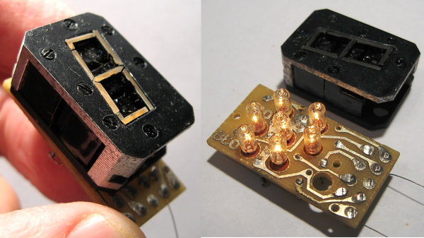
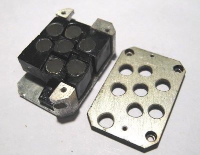
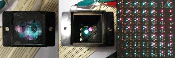
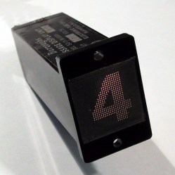
Ever heard of a sphericular display? [AnubisTTP] laid hands on a (damaged) Burroughs SD-11 Sphericular Display and tore down the unusual device to see what was inside. It’s a type of projection display with an array of bulbs at the back and a slab of plastic at the front, and the rest is empty space. The usual expected lenses and slides are missing… or are they? It turns out that the thin display surface at the front of the unit is packed with a two- dimensional 30 x 30 array of small lenses, a shadow mask, and what can be thought of as a high-density pixel mask. The SD-11 was cemented together and clearly not intended to be disassembled, but [AnubisTTP] managed to cut things carefully apart in order to show exactly how these fascinating devices solved the problem of displaying digits 0-9 (with optional decimal points) on the single small screen without separate digit masks and lenses to bend the light paths around.

The “pixel mask” of the SD-11

The face of the display can be thought of as a 30×30 array of pixels, with each of the microlenses in the lens array acting as one of these pixels. But these pixels are not individually addressable, they light up only in fixed patterns determined by the “pixel mask”. How exactly does this happen? With each microlens in the array showing a miniature of the bulb pattern at the rear of the display, a fixed image pattern can be shown at the front by putting a mask over each lens: if a certain bulb at the rear needs to result in a lit pixel at the front, that mask has a hole in that bulb’s location. If not, there is no hole and the light is blocked. Just as the compound lens is a two-dimensional array of microlenses, so is the light mask really a two-dimensional array of smaller masks: exactly one per microlens. In this way the “pixel mask” is how each bulb at the rear results in a fixed pattern (digits, in this case) projected at the front.

The Burroughs SD-11 Sphericular Display was very light, containing mostly empty space where other projection displays had lenses and light masks. It turns out that the SD-11 operates using the same principles as other projection displays, but by using a high-density light mask and a compound lens array it does so by an entirely different method. It’s a great peek into one of the different and fascinating ways problems got solved before modern display solutions became common.

I Am An Iconoscope

We’d never seen an iconoscope before. And that’s reason enough to watch the quirky Japanese, first-person video of a retired broadcast engineer’s loving restoration. (Embedded below.)

Quick iconoscope primer. It was the first video camera tube, invented in the mid-20s, and used from the mid-30s to mid-40s. It worked by charging up a plate with an array of photo-sensitive capacitors, taking an exposure by allowing the capacitors to discharge according to the light hitting them, and then reading out the values with another electron scanning beam.

The video chronicles [Ozaki Yoshio]’s epic rebuild in what looks like the most amazingly well-equipped basement lab we’ve ever seen. As mentioned above, it’s quirky: the iconoscope tube itself is doing the narrating, and “my father” is [Ozaki-san], and “my brother” is another tube — that [Ozaki] found wrapped up in paper in a hibachi grill! But you don’t even have to speak Japanese to enjoy the frame build and calibration of what is probably the only working iconoscope camera in existence. You’re literally watching an old master at work, and it shows.

Continue reading “I Am An Iconoscope”

Retrotechtacular: The Aerolux Light Corporation

The humble incandescent lightbulb is an invention just about anyone born in the 20th Century is more than familiar with. But it’s not the be all and end all of lighting technology – there are neon lights, compact fluorescent bulbs, and even LEDs are finally being adopted for interior lighting. But with the endless march forward, there are vintage throwbacks to the past – how many hipster cafes have you been to lately with great big industrial-looking filament bulbs hanging from the ceiling?

Even when switched off, they have a striking appearance.

However, that’s not all history has to give us. These gas discharge bulbs from yesteryear are absolute works of art.

The bulbs contain delicate floral sculptures in metal, coated with phosphor, and the bulbs are filled with neon or argon gas. Applying mains voltage to the electrodes inside the bulb causes the phospor to fluoresce, creating a glowing flower that is hauntingly beautiful.

These bulbs were manufactured by the Aerolux Light Company, from the 1930s to the 1970s. Once upon a time, they could be had for as little as 20 cents a bulb – nowadays you’re likely to pay over $50 on eBay or Etsy. The bulbs work by the glow discharge effect, not at all dissimilar to garden variety neon lamps.

While it’s not easy, it is possible to make your own vacuum tubes. Maybe it’s time to order some phospor powder and a tank of neon and get to work? Be sure to document your attempt on Hackaday.io.

Thanks to [Itay Ramot] for the tip!