Hands On: Bus Pirate 5

If you’ve been involved with electronics and hardware hacking for awhile, there’s an excellent chance you’ve heard of the Bus Pirate. First introduced on the pages of Hackaday back in 2008 by creator Ian Lesnet, the open hardware multi-tool was designed not only as away to easily tap into a wide array of communication protocols, but to provide various functions that would be useful during hardware development or reverse engineering. The Bus Pirate could talk to your I2C and SPI devices, while also being able to measure frequencies, check voltages, program chips, and even function as a logic analyzer or oscilloscope.

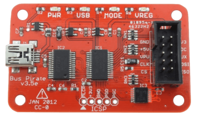
Bus Pirate 3, circa 2012

The Bus Pirate provided an incredible number of tools at a hobbyist-friendly price, and it wasn’t long before the device became so popular that it achieved a milestone which only a few hardware hacking gadgets can boast: its sales started to get undercut by cheap overseas clones. Of course, as an open hardware device, this wasn’t really a problem. If other companies wanted to crank out cheap Bus Pirates, that’s fine. It freed Ian up to research a next-generation version of the device.

But it turns out that was easier said than done. It’s around this point that the Bus Pirate enters what might be considered its Duke Nukem Forever phase. It took 15 years to release the sequel to 1996’s Duke Nukem 3D because the state-of-the-art in video games kept changing, and the developers didn’t want to be behind the curve. Similarly, Ian and his team spent years developing and redeveloping versions of the Bus Pirate that utilized different hardware platforms, such as the STM32 and ICE40 FPGA. But each time, there would be problems sourcing components, or something newer and more interesting would be released.

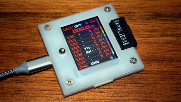
But then in 2021 the Raspberry Pi Pico hit the scene, and soon after, the bare RP2040 chip. Not only were the vast I/O capabilities of the new microcontroller a perfect fit for the Bus Pirate, but the chip was cheap and widely available. Finally, after years of false starts, the Bus Pirate 5 was born.

I was able to grab one of the first all-new Bus Pirates off the production line in January, and have been spending the last week or so playing around with it. While there’s definitely room for improvement on the software side of things, the hardware is extremely promising, and I’m very excited to be see how this new chapter in the Bus Pirate story plays out.

Continue reading “Hands On: Bus Pirate 5”

A Dashboard Outside The Car

One of the biggest upsides of open communications standards such as CAN or SPI is that a whole world of vehicle hacking becomes available, from simple projects like adding sensors or computers to a car or even building a complete engine control unit from the ground up. The reverse is true as well; sensors and gauges using one of these protocols can be removed from a car and put to work in other projects. That’s the idea that [John] had when he set about using a vehicle’s dashboard as a information cluster for his home.

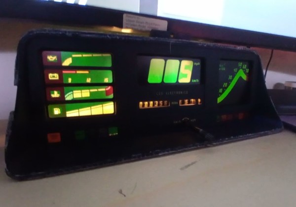
The core of the build is an Astra GTE dashboard cluster, removed from its host vehicle, and wired to an Arduino-compatible board, in this case an ESP32. The code that [John] wrote bit-bangs an SPI bus and after some probing is able to address all of the instrument gauges on the dashboard. For his own use at home, he’s also configured it to work with Home Assistant, where each of the gauges is configured to represent something his home automation system is monitoring using a bit mask to send data to specific dials.

While this specific gauge cluster has a lot of vehicle-specific instrumentation and needs a legend or good memory to tie into a home automation system without any other modification, plenty of vehicle gauges are more intuitive and as long as they have SPI they’d be perfect targets for builds that use this underlying software. This project takes a similar tack and repurposes a few analog voltmeters for home automation, adding a paper background to the meters to make them easier to read.

Continue reading “A Dashboard Outside The Car”

Bypassing Bitlocker With A Logic Analzyer

Security Engineer [Guillaume Quéré] spends the day penetration testing systems for their employer and has pointed out and successfully exploited a rather obvious weakness in the BitLocker full volume encryption system, which as the linked article says, allows one to simply sniff the traffic between the discrete TPM chip and CPU via an SPI bus. The way Bitlocker works is to use a private key stored in the TPM chip to encrypt the full volume key that in turn was used to encrypt the volume data. This is all done by low-level device drivers in the Windows kernel and is transparent to the user.

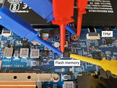
TPM chip pins too small? Just find something else on the bus!

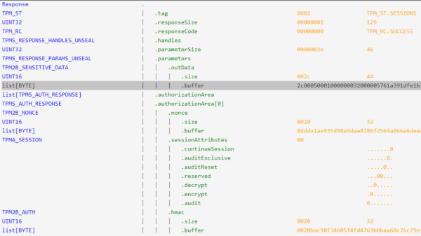
The whole point of BitLocker was to prevent access to data on the secured volume in the event of a physical device theft or loss. Simply pulling the drive and dropping it into a non-secured machine or some other adaptor would not provide any data without the key stored by the TPM. However, since that key must pass as plaintext from the TPM to the CPU during the boot sequence, [Guillaume] shows that it is quite straightforward — with very low-cost tools and free software — to simply locate and sniff out this TPM-to-CPU transaction and decode the datastream and locate the key. Using little more than a cheapo logic analyser hooked up to some conveniently large pins on a nearby flash chip (because the SCK, MISO, and MOSI pins are shared with the TPM) the simple TIS was decoded enough to lock onto the bytes of the TPM frame. This could then be decoded with a TPM stream decoder web app, courtesy of the TPM2-software community group. The command to look for is the TPM_CC.Unseal which is the request from the CPU to the TPM to send over that key we’re interested in. After that just grabbing and decoding the TPM response frame will immediately reveal the goods.

Continue reading “Bypassing Bitlocker With A Logic Analzyer”

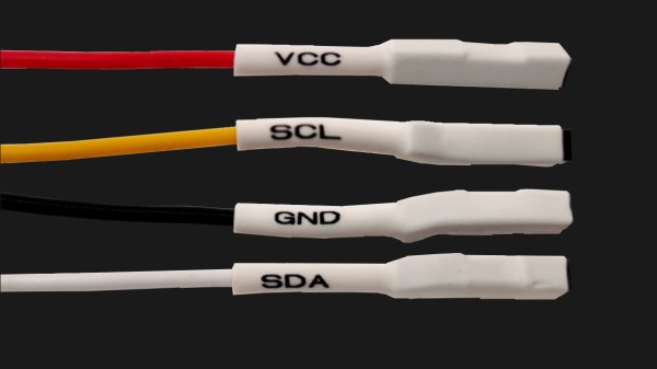
Four jumper wires with white heatshrink on them, labelled VCC, SCL, SDA and GND

Three Pitfalls In I2C Everyone Wishes Weren’t There

The best part of I2C is that it is a bus that is available just about anywhere, covering a vast ecosystem of devices that offer it as a hardware-defined interface, while being uncomplicated enough that it can also be implemented purely in software on plain GPIO pins. Despite this popularity, I2C is one of those famous informal standards that feature a couple of popular implementations, while leaving many of the details such as exact timing, bus capacitance and other tedious details to the poor sod doing the product development. Thus it is that we end up with articles such as a recent one on the tongue-twisting [pair of pared pears] blog, covering issues found while implementing an I2C slave.

As with any shared bus, whether multi-master or not, figuring out when the bus is clear is a fun topic, yet one which can cause endless headaches. One issue here comes from a feature that the SMBus version of I2C calls quick read/write. This allows for the rapid transfer of some data. Still, depending on the data returned by the slave, it may appear to the master that nothing is happening yet, since SDA is being held low by the slave until the stop condition, essentially locking the bus.

I2C hold times example.

Where things get even more exciting comes generally in the form of what logic analyzers love to traumatically call a ‘spurious start/stop condition’. This refers to the behavior of SDA and SCL, with SDA going low before SCL indicating an error. This can occur due to a hold time that’s too low, causing other devices on the bus to miss the transition. Here SMBus defines a transition time of 300 ns, while I2C calls for 0 seconds, but it’s now suggested to delay calling a start/stop condition until a delay of 300 ns has passed. Essentially, it would seem that implementing a hold time is the way forward until evidence to the contrary appears.

The third pitfall pertains to the higher-speed modes of I2C, including Fast-Mode (FM) and Fast-Mode Plus (FM+). Backward compatibility with these higher speed versions is absent to spotty. Although FM+ (introduced by NXP in 2007) is supposed to be backward compatible with slower speeds, effectively the timing requirement differences between the FM+ and FM standards are too large to compensate for. At least in the current versions of the standards, but one of the joys of I2C is that there’s always another new set of revisions to look forward to.

Reverse Engineering A Better Night’s Sleep

All you want is a decent night’s sleep, so you decide to invest in one of those fancy adjustable beds. At first, it’s fine — being able to adjust the mattress to your needs on the fly is a joy, and yet…something isn’t quite right. Something nags at you every night, thwarting your slumber and turning your dreams of peaceful sleep into a nightmare once you realize your bed has locked you into a vertically integrated software ecosystem from which there’s no escape.

Or is there? That’s what [Chris Laplante] wanted to know, and why he reverse-engineered his Tempur-Pedic remote control. As many products these days do, his bed was touted as having an Android application for smartphone adjustability, but alas, the app hasn’t been updated since 2014 (!) and doesn’t appear to work on modern phones. [Chris] decided to take matters into his own hands and build a gateway to talk to the bed using its native RF protocol.

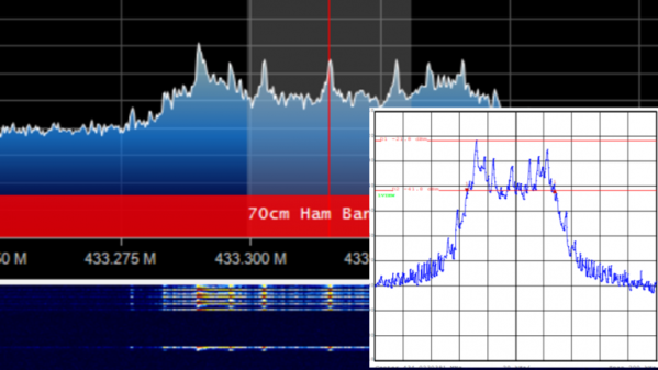
Most good reverse engineering stories start with research, and this one is no exception. Digging into the FCC database revealed a wealth of clues, such as the frequency — 433-MHz ISM band, no surprise — and even spectrum analyzer screenshots of the remote’s signals. A HackRF One revealed more about the signals, but it turned out that sniffing in on the SPI bus between the microcontroller and the Si4431 RF transceiver with a Salae logic analyzer was more fruitful, allowing him to dig into the packet structure.

The engineers at Tempur-Pedic threw quite a few challenges at [Chris], like an application-level CRC in addition to the CRC used by the Si4431, and interesting complications to control the massage features of the bed. In the end, [Chris] managed to get a pretty complete snapshot of the conversation between the bed and the remote, and is now in the process of building a gateway that’ll actually connect to his phone, plus integrate into his home automation system. We’re looking forward to updates on that.

Interlaken Want To Connect All The Chips

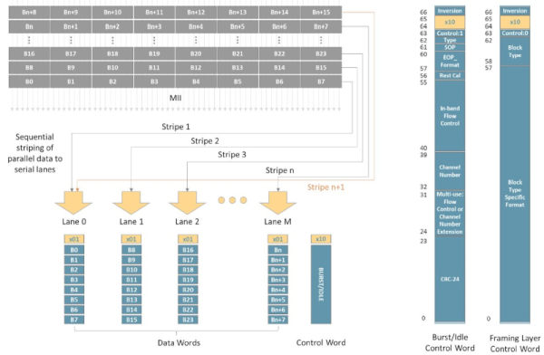
One of the problems with designing things on a chip is finding a good way to talk to the outside world. You may not design chips yourself, but you care because you want to connect your circuits — including other chips — to the chips in question. While I2C and SPI are common solutions, today’s circuits are looking for more bandwidth and higher speeds, and that’s where Interlaken comes in. [Comcores] has an interesting post on the technology that blends the best of SPI 4.2 and XAUI.

The interface is serial, as you might expect. It can provide both high-bandwidth and low-latency multi-channel communications. Interlaken was developed by Cisco and Cortina Systems in 2006 and has since been adopted by other industry-leading companies. Its latest generation supports speeds as high as 1.2 Tbps.

Continue reading “Interlaken Want To Connect All The Chips”

Low-Cost Display Saved By RP2040

Anyone looking for components for electronics projects, especially robotics, microcontrollers, and IoT devices, has likely heard of Waveshare. They are additionally well-known suppliers of low-cost displays with a wide range of resolutions, sizes, and capabilities, but as [Dmitry Grinberg] found, they’re not all winners. He thought the price on this 2.8-inch display might outweigh its poor design and lack of documentation, and documented his process of bringing it up to a much higher standard with a custom driver for it.

The display is a 320×240 full-color LCD which also has a touchscreen function, but out-of-the-box only provides documentation for sending data to it manually. This makes it slow and, as [Dmitry] puts it, “pure insanity”. His ultimate solution after much poking and prodding was to bit-bang an SPI bus using GPIO on an RP2040 but even this wasn’t as straightforward as it should have been because there are a bunch of other peripherals, like an SD card, which share the bus. Additionally, an interrupt is needed to handle the touchscreen since its default touch system is borderline useless as well, but after everything was neatly stitched together he has a much faster and more versatile driver for this display and is able to fully take advantage of its low price.

For anyone else attracted to the low price of these displays, at least the grunt work is done now if a usable driver is needed to get them up and running. And, if you were curious as to what [Dmitry] is going to use this for, he’s been slowly building up a PalmOS port on hardware he’s assembling himself, and this screen is the perfect size and supports a touch interface. We’ll keep up with that project as it progresses, and for some of [Dmitry]’s other wizardry with esoteric displays make sure to see what he’s done with some inexpensive e-ink displays as well.