This Pogo Pin Test Fixture Keep Your SMDs From Taking Flight

There’s no denying how useful surface mount technology is, and how enabling the ability to make really small circuits has become. It comes at a price, though; most of us probably know what it’s like for the slightest wrong move to send a part the size of a grain of sand into another dimension.

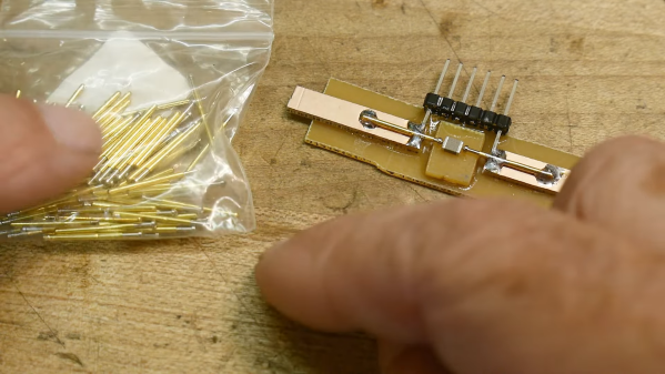
To help make testing these parts a little easier, [IMSAI Guy] has come up with this clever little SMD test fixture. It’s designed to hook up to another custom board, which in turn connects to a wonderful old Hewlett-Packard 4275A LCR meter. The jig is based on two pogo pins mounted directly across from each other on a scrap of single-clad PCB. The spring-loaded contacts, which short together when not in use, are pulled apart to load an SMD part, like the 1-μH inductors shown in the video below. The pins hold the component firmly and make good electrical contact, allowing hands-free testing without the risk of an errant touch of the test probes sending it flying.

While the test fixture works well for larger SMDs, we could see this being a bit fussy for smaller parts. That would be easy enough to fix with perhaps some 3D-printed arms that retract the pogo pins symmetrically, holding them open until the part is loaded. A centering fixture might help too, as would a clear shield to contain any parts that get the urge to go for a ride. But, for the tactical application [IMSAI Guy] has in mind, this sure seems like enough.

Just getting into surface mount? If so, you might want to check out this handy guide to the often cryptic markings used on SMD parts.

Continue reading “This Pogo Pin Test Fixture Keep Your SMDs From Taking Flight”

A Mobile Phone From 1985

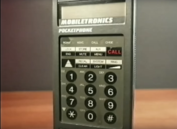
It might seem quaint through the lends of history we have the luxury of looking through, but in the mid 1980s it was a major symbol of status to be able to communicate on-the-go. Car phones and pagers were cutting-edge devices of the time, and even though there were some mobile cellular telephones, they were behemoths compared to anything we would recognize as a cell phone today. It wasn’t until 1985 that a cell phone was able to fit in a pocket, and that first device wasn’t just revolutionary because of its size. It made a number of technological advancements that were extremely impressive for its time, and [Janus Cycle] takes us through some of those in this teardown video.

The Technophone came to us from Great Britain by way of a former Ericsson engineer named Nils Mårtensson. It was able to achieve its relatively small stature using a surface-mount PCB, which was a cutting-edge manufacturing process for the time. Not only did it use surface-mount components and boards, but the PCB itself has 12 layers and two sides and hosts two custom Technophone chips. The phone is relatively modular as well, with the screen, battery pack, and other components capable of easily disconnecting from the main board. Continue reading “A Mobile Phone From 1985”

Surface Mount Breathing Light PCB, using LM358 op-amp

Surface-Mount Light Breathes Life Into Your Project

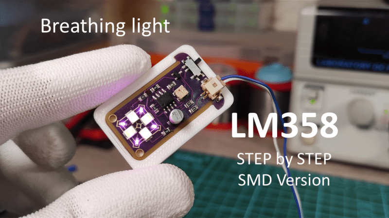
If you’ve ever seen those gadgets with the “breathing light” LEDs on them and wondered how to do it, then [DIY GUY Chris] can show you how to design your own surface-mount version, using only analogue electronics.

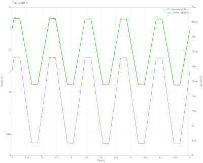
Simulation trace showing the LED breathing light circuit operating. Traces for voltage and current are shown over a few seconds
The LED current tracks up and down in an approximately triangular-wave pattern

The circuit itself is built around a slow triangular-wave oscillator, that ramps the current up and down in the LEDs to make it look as if the lights are breathing in and out. The overall effect is rather pleasing, and the oscillation speed can be adjusted using the on-board potentiometer.

This project is actually an update to a previous version that used through-hole components (also shown in the video below), and goes to show that revisiting completed projects can give them a new lease of life. It also shows how easy it has become to design and order custom circuit boards these days. It’s not so long ago that a project like this would have been either made on stripboard or etched from copper-plated FR4 in a bubbling tank of acid!

If you have revisited an old project that you’re proud of and would like to show others, why not drop us a message on our tips line?

We have covered some other options for breathing LEDs in the past, such as this digital logic version, and this Arduino library that has a host of other effects to choose from, too. Continue reading “Surface-Mount Light Breathes Life Into Your Project”

Photo of Pixel Pump Pick & Place Machine

Pixel Pump Pick & Place Positions Parts Precisely

You’ve finally decided to take the plunge and build a board with surface-mount parts. After carefully dispensing the solder paste with a syringe, it’s time to place the parts. You take up your trusty tweezers and reach to grab a SOIC-14 logic IC—only there’s not a great way to grab it. The IC is too long to grab one way and has leads obstructing the other. You work around the leads, drop the IC into place, and then pick up an 0402 resistor. You gently set the resistor into your perfectly dispensed solder paste, pull the tweezers away, and the resistor has stuck to your slightly magnetic tweezers. [Robin Reiter] realized that hobbyists and small manufacturers needed a better way to assemble their surface-mount designs, so he’s building the Pixel Pump Pick & Place, an open-source vacuum assembly tool.

Vacuum assembly tools use a blunt-tipped needle and suction to pick up surface-mount parts. Pressing an attached foot pedal disables the vacuum, allowing the part to be gently released. [Robin] thought to include a few thoughtful features to make the Pixel Pump even more useful. It has adjustable suction presets and a self-cleaning feature to blow out any solder paste you accidentally suck up. Most of the non-electronic parts are 3D printed, and [Robin] intends to make the entire design open-source.

[Robin] has a long history of designing tools to make surface-mount assembly easier—you may remember his 3D-printed magazines for dispensing surface-mount parts. If you want to take your PCB assembly setup to the next level, check out the PnPAssist, which shines a laser crosshair right where you should put each part.

BGA Soldering And Inspection

If you want to build cool things these days, you’ve probably had to master surface mount electronics. However, for many people, ball grid array (BGA) is still intimidating. Have a look at [VoltLog’s] video about his techniques for soldering BGA and inspecting that you managed to do it right.

He’s got quite a few tips about things like surface finish and flux selection. It looks easy when he does it. Of course, having a good PCB with good registration markings will help too.

Continue reading “BGA Soldering And Inspection”

Manual Pick And Place Turntable Makes Board Assembly Easier

Surface mount devices were once upon a time considered a huge imposition for the electronics hobbyist. Tiny, difficult to solder by hand, and barely even labelled, many wondered whether the pastime was about to hit a brick wall entirely. Instead, enterprising hackers and makers set about learning new tricks and techniques to work with the technology, and we’ve never looked back since. [Seon] is one such enthusiast, and has built a useful turntable for making manually picking and placing boards easier. (Video, embedded below.)

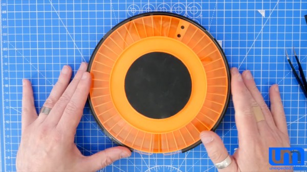
The design is something [Seon] has refined gradually over time, having built two initial versions of the turntable before finally feeling ready to do a wider public release with version 3. It consists of a rotating caddy that has radial slots that hold all the tiny SMD parts, that can be labelled for easy parts identification. There’s also an acrylic window that ensures only one segment of the caddy is open at a time, to avoid accidentally dropping similar, tiny looking parts into adjacent slots – a big improvement over the first design. There’s then a smaller rotating central pad upon which a PCB can be placed, ready to receive parts.

Files are available on Github for those wanting to build their own. [Seon] does a great job explaining how the final design came about, after populating hundreds of boards on his earlier designs and learning their limitations. If doing it by hand just doesn’t cut it for you, though, you can always built a fully automated PnP.

Continue reading “Manual Pick And Place Turntable Makes Board Assembly Easier”

Learn Bil Herd’s DIY Surface Mount Assembly Process

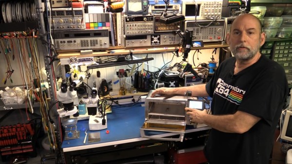
You can do your own Surface Mount Technology based PCB assembly with just a handful of tools and some patience. At the heart of my SMT process is stopping to inspect the various steps all while trying to maintain a bit of cleanliness in the process.

Surface mount or Surface Mount Technology (SMT) is the modern way to assemble Printed Circuit Boards (PCB) and is what is commonly seen when opening a modern piece of tech. It’s much smaller than the older Through-Hole (TH) technology where the component leads were inserted into holes in PCB, and act we called “stuffing” since we had to stuff the components into the holes.

A few specialized tools make this a lot easier, but resourceful hackers will be able to pull together a solder paste stencil jig, vacuum tweezers, and a modified toaster oven with a controller that can follow the reflow profile of the solder paste. Where you shouldn’t skimp is on the quality, age, and storage of the solder paste itself.

Join me after the break for my video overview of the process I use in my workshop, along with details of every step of my SMT assembly process.

Continue reading “Learn Bil Herd’s DIY Surface Mount Assembly Process”