The Fastest Fourier Transform In The West

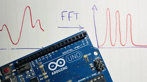
An interesting aspect of time-varying waveforms is that by using a trick called a Fourier Transform (FT), they can be represented as the sum of their underlying frequencies. This mathematical insight is extremely helpful when processing signals digitally, and allows a simpler way to implement frequency-dependent filtration in a digital system. [klafyvel] needed this capability for a project, so started researching the best method that would fit into an Arduino Uno. In an effort to understand exactly what was going on they have significantly improved on the code size, execution time and accuracy of the previous crown-wearer.

A complete real-time Fourier Transform is a resource-heavy operation that needs more than an Arduino Uno can offer, so faster approximations have been developed over the years that exchange absolute precision for speed and size. These are known as Fast Fourier Transforms (FFTs). [klafyvel] set upon diving deep into the mathematics involved, as well as some low-level programming techniques to figure out if the trade-offs offered in the existing solutions had been optimized. The results are impressive.

Fastest FFT code benchmarking results in ms
Benchmarking results showing speed of implementation versus the competition (ApproxFFT)

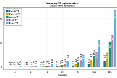
Not content with producing one new award-winning algorithm, what is documented on the blog is a masterclass in really understanding a problem and there are no less than four algorithms to choose from depending on how you rank the importance of execution speed, accuracy, code size or array size.

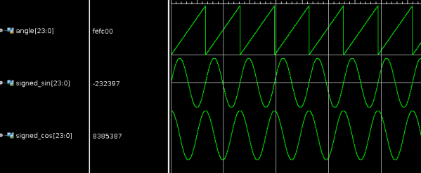
Along the way, we are treated to some great diversions into how to approximate floats by their exponents (French text), how to control, program and gather data from an Arduino using Julia, how to massively improve the speed of the code by using trigonometric identities and how to deal with overflows when the variables get too large. There is a lot to digest in here, but the explanations are very clear and peppered with code snippets to make it easier and if you have the time to read through, you’re sure to learn a lot!  The code is on GitHub here.

If you’re interested in FFTs, we’ve seen them before around these parts. Fill your boots with this link of tagged projects.

Apollo 11 Trig Was Brief

In this day and age where a megabyte of memory isn’t a big deal, it is hard to recall when you had to conserve every byte of memory. If you are a student of such things, you might enjoy an annotated view of the Apollo 11 DSKY sine and cosine routines. Want to guess how many lines of code that takes? Try 35 for both.

Figuring out how it works takes a little knowledge of how the DSKY works and the number formats involved. Luckily, the site has a feature where you can click on the instructions and see comments and questions from other reviewers.

Continue reading “Apollo 11 Trig Was Brief”

Looking For Pi In The 8087 Math Coprocessor Chip

Even with ten fingers to work with, math can be hard. Microprocessors, with the silicon equivalent of just two fingers, can have an even harder time with calculations, often taking multiple machine cycles to figure out something as simple as pi. And so 40 years ago, Intel decided to give its fledgling microprocessors a break by introducing the 8087 floating-point coprocessor.

If you’ve ever wondered what was going on inside the 8087, wonder no more. [Ken Shirriff] has decapped an 8087 to reveal its inner structure, which turns out to be closely related to its function. After a quick tour of the general layout of the die, including locating the microcode engine and ROM, and a quick review of the NMOS architecture of the four-decade-old technology, [Ken] dug into the meat of the coprocessor and the reason it could speed up certain floating-point calculations by up to 100-fold. A generous portion of the complex die is devoted to a ROM that does nothing but store constants needed for its calculation algorithms. By carefully examining the pattern of NMOS transistors in the ROM area and making some educated guesses, he was able to see the binary representation of constants such as pi and the square root of two. There’s also an extensive series of arctangent and log2 constants, used for the CORDIC algorithm, which reduces otherwise complex transcendental calculations to a few quick and easy bitwise shifts and adds.

[Ken] has popped the hood on a lot of chips before, finding butterflies in an op-amp and reverse-engineering a Sinclair scientific calculator. But there’s something about seeing constants hard-coded in silicon that really fascinates us.

CORDIC Brings Math To FPGA Designs

We are always excited when we see [Hamster] post an FPGA project, because it is usually something good. His latest post doesn’t disappoint and shows how he uses the CORDIC algorithm to generate very precise sine and cosine waves in VHDL. CORDIC (Coordinate Rotation Digital Computer; sometimes known as Volder’s algorithm) is a standard way to compute hyperbolic and trigonometric functions. What’s nice is that the algorithm only requires addition, subtraction, bit shifts, and a lookup table with an entry for each bit of precision you want. Of course, if you have addition and negative numbers, you already have subtraction. This is perfect for simple CPUs and FPGAs.

[Hamster] not only has the VHDL code but also provides a C version if you find that easier to read. In either case, the angle is scaled so that 360 degrees is a full 24-bit word to allow the most precision. Although it is common to compute the result in a loop, with the FPGA, you can do all the math in parallel and generate a new sample on each clock cycle.

Continue reading “CORDIC Brings Math To FPGA Designs”

Measure Laser Wavelength With A CD And A Tape Measure

Obviously the wavelength of a laser can’t be measured with a scale as large as that of a carpenter’s tape measure. At least not directly and that’s where a Compact Disc comes in. [Styropyro] uses a CD as a diffraction grating which results in an optical pattern large enough to measure.

A diffraction grating splits a beam of light up into multiple beams whose position is determined by both the wavelength of the light and the properties of the grating. Since we don’t know the properties of the grating (the CD) to start, [Styropyro] uses a green laser as reference. This works for a couple of reasons; the green laser’s properties don’t change with heat and it’s wavelength is already known.

It’s all about the triangles. Well, really it’s all about the math and the math is all about the triangles. For those that don’t rock out on special characters [Styropyro] does a great job of not only explaining what each symbol stands for, but applying it (on camera in video below) to the control experiment. Measure the sides of the triangle, then use simple trigonometry to determine the slit distance of the CD. This was the one missing datum that he turns around and uses to measure and determine his unknown laser wavelength.

Continue reading “Measure Laser Wavelength With A CD And A Tape Measure”

Tilt Compensation When Reading A Digital Compass

If you’re familiar with using a compass (the tool that points to magnetic north, not the one that makes circles) the concept of holding the device level makes sense. It must be level for the needle to balance and rotate freely. You just use your eyes to make sure you’re holding the thing right. Now think of a digital compass. They work by measuring the pull of a magnetic field, and have no visual method of showing whether they’re level or not. To ensure accurate readings you might use an accelerometer to compensate for a tilted magnetometer.

The process involves taking measurements from both an accelerometer and a magnetometer, then performing calculations with that data to get a true reading. Luckily the equations have been figured out for us and we don’t need to get too deep into trigonometry. You will, however, need to use sine, cosine, and arctangent in your calculations. These should be available in your programming language of choice. Arduino (used here) makes use of the avr-libc math library to perform the calculations.