Japanese Lab Builds 5-Axis 3D Printer

A Japanese lab is investing some time in the possibilities of a 5-axis 3D printer. They show it printing using five axis as well as doing finish machining on a printed part. We’ve covered parts of why this is the right direction to go for 3D printing in another post.

It looks like they have modified an existing industrial machining center for use with a 3D printing nozzle. This feels like cheating, but it’s the right way to go if you want to start playing with the code early. The machines are intensely accurate and precise. After all, building a five axis machine is a well known science, 3D printing with one opens a whole new field of research.

There isn’t too much to show in the video, other than it’s possible and people are doing it. The Five-axis 3D printing and machining is uninteresting, we have been able to machine plastic for a long time.

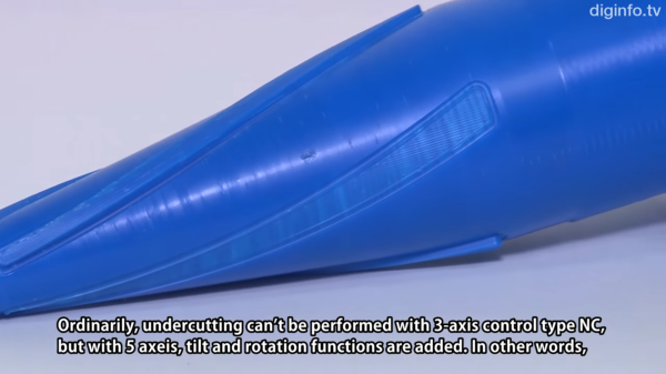
However, they show one blue part in which the central axis of the part was printed vertically, but revolute splines along its outer perimeter were printed normal to the surface of the already printed 3D part. Which is certainly not commonly done. Video after the break.

Continue reading “Japanese Lab Builds 5-Axis 3D Printer”

Centennial Birthday Of Claude E. Shannon The Math And EE Pioneer

Dr. Claude E. Shannon was born 100 years ago tomorrow. He contributed greatly to the fields of engineering, communications, and computer science but is not a well known figure, even to those in the field. However, his work touches us all many times each day. The network which delivered this article to your computer or smartphone was designed upon important theories developed by Dr. Shannon.

Shannon was born and raised in Michigan. He graduated from the University of Michigan with degrees in Mathematics and Electrical Engineering. He continued his graduate studies at Massachusetts Institute of Technology (MIT) where he obtained his MS and PhD. He worked for Bell Laboratories on fire-control systems and cryptography during World War II and in 1956 he returned to MIT as a professor.

shannon-0Shannon’s first impactful contribution was his masters thesis which took the Boolean Algebra work of George Boole and applied it to switching circuits (then made up of relays). Before his work there was no formal basis for the analysis of switching systems, like telephone networks or elevator control systems. Shannon’s thesis developed the use of symbolic notation to represent networks and applied simplifying rules to optimize the system. These same rules later translated to vacuum tube and transistor logic aiding in the development of today’s computer systems. The thesis — A Symbolic Analysis of Relay and Switching Circuits — was completed in 1937 and subsequently published in 1938 in the Transactions of the American Institute of Electrical Engineers.

Shannon’s doctoral work continued in the same vein of applying mathematics someplace new, this time to genetics. Vannevar Bush, his advisor, commented, “It occurred to me that, just as a special algebra had worked well in his hands on the theory of relays, another special algebra might conceivably handle some of the aspects of Mendelian heredity”. Shannon’s work again is revolutionary, providing a mathematical basis for population genetics. Unfortunately, it was a step further than geneticists of time could take. His work languished, although interest increased over time.

Continue reading “Centennial Birthday Of Claude E. Shannon The Math And EE Pioneer”

The Gerber Behind Gerber Files

When we create a printed circuit board, the chances are these days that we’ll export it through our CAD package’s CAM tool, and send the resulting files to an inexpensive PCB fabrication house. A marvel of the modern age, bringing together computerised manufacturing, the Internet, and globalised trade to do something that would have been impossible only a few years ago without significant expenditure.

Those files we send off to China or wherever our boards are produced are called Gerber files. It’s a word that has become part of the currency of our art, “I’ll send them the Gerbers” trips off the tongue without our considering the word’s origin.

This morning we’re indebted to [drudrudru] for sending us a link to an EDN article that lifts the lid on who Gerber files are named for. [H. Joseph Gerber] was a prolific inventor whose work laid the ground for the CNC machines that provide us as hackers and makers with so many of the tools we take for granted. Just think: without his work we might not have our CNC routers, 3D printers, vinyl cutters and much more, and as for PCBs, we’d still be fiddling about with crêpe paper tape and acetate.

An Austrian Holocaust survivor who escaped to the USA in 1940, [Gerber] began his business with an elastic variable scale for performing numerical conversions that he patented while still an engineering student. The story goes that he used the elastic cord from his pyjamas to create the prototype. This was followed by an ever-more-sophisticated range of drafting, plotting, and digitizing tools, which led naturally into the then-emerging CNC field. It is probably safe to say that in the succeeding decades there has not been an area of manufacturing that has not been touched by his work.

So take a look at the article, read [Gerber]’s company history page, his Wikipedia page, raise a toast to the memory of a great engineer, and never, ever, spell “Gerber file” with a lower-case G.

Connect All Your IoT Through Your Pi 3

If you’re playing Hackaday Buzzword Bingo, today is your lucky day! Because not only does this article contain “Pi 3” and “IoT”, but we’re just about to type “ESP8266” and “home automation”. Check to see if you haven’t filled a row or something…

Seriously, though. If you’re running a home device network, and like us you’re running it totally insecurely, you might want to firewall that stuff off from the greater Interwebs at least, and probably any computers that you care about as well. The simplest way to do so is to keep your devices on their own WiFi network. That shiny Pi 3 you just bought has WiFi, and doesn’t use so much power that you’d mind leaving it on all the time.

Even if you’re not a Linux networking guru, [Phil Martin]’s tutorial on setting up the Raspberry Pi 3 as a WiFi access point should make it easy for you to use your Pi 3 as the hub of your IoT system’s WiFi. He even shows you how to configure it to forward your IoT network’s packets out to the real world over wired Ethernet, but if you can also use the Pi 3 as your central server, this may not even be necessary. Most of the IoT services that you’d want are available for the Pi.

Those who do want to open up to the world, you can easily set up a very strict firewall on the Pi that won’t interfere with your home’s normal WiFi. Here’s a quick guide to setting up iptables on the Pi, but using even friendlier software like Shorewall should also get the job done.

Still haven’t filled up your bingo card yet? “Arduino!”

Refreshable Braille Display And Braille Keyboard

Only about 10% of blind people around the world can read Braille. One primary reason is the high cost of Braille displays. The cost is a result of their complexity and reliability – required to ensure that they are able to handle wear and tear.

[Vijay] has been working since 3 years on a Refreshable Braille Display but has only recently been able to make some substantial progress after teaming up with [Paul D’souza]. During his initial experiments, he used dot matrix printer heads, but the current version uses tiny vibration motors as used in mobile phones. He’s converting rotary motion of the tiny motors in to linear movement for pushing the Braille “cell” pins up and down. The eccentric weight on the vibration motor is replaced with a shaped cam. Continuous rotation of the cam is limited by a stopper, which is part of the 3D printed housing that holds the motors. Another 3D printed part has three cam followers, levers, springs and Braille pins rolled in one piece, to create half a Braille cell. Depending on the cam position, the pins are either pushed up or down. One Braille cell module consists of two cam follower pieces, a housing for six vibration motors, and a cover plate. Multiple modules are chained together to form the display.

The next step would be to work on the electronics – in particular ensuring that he is able to control the motor movement in both directions in a controlled manner. Chime in with your comments if you have any ideas. The 3D design files are available from his Dropbox folder.

Continue reading “Refreshable Braille Display And Braille Keyboard”

Ping Pong Spectrum Analyzer

A spectrum analyzer is a pretty useful tool for working with signals where the size of the frequency components matter. Usually, the display is a screen. Sometimes, you see it done with LEDs. [Mag Laboratories] did it with ping pong balls.

The device uses a processor to calculate a Fourier transform, cutting an audio signal into 16 frequency bands. The processor converts each of these values to a PWM output that drives small fans. The fans blow the ping pong ball up the tube proportional to the fan speed. You can see the result in the video below.

Continue reading “Ping Pong Spectrum Analyzer”

Colin Furze Flies The Dangerous Skies

To quote our tipster: “Furze is my hero … You just need to know how to weld and have zero consideration for your personal well-being.” We’re not exactly sure that he has no consideration, but [Colin Furze] definitely pulls off some dangerous hacks. This time? Two-engine hoverbike. We don’t have to tell you to watch the video, do we? Continue reading “Colin Furze Flies The Dangerous Skies”