Raspberry Pi Zero Becomes Mighty Miniature Minecraft Machine

In a clever bit of  miniaturization, [JediJeremy] has nearly completed a gyro-mouse controller for a Raspberry Pi Zero! Ultimately this will be a wearable Linux-watch but along the way he had some fun with the interface.

Using the MPU6040 gyroscope/accelerometer card from a quadcopter, [JediJeremy] spent a week writing the driver to allow it to function as a mouse. Strapping an Adafruit 1.5″ PAL/NTSC LCD screen and its driver board to the Zero with rubber bands makes this one of the smallest functional computer and screen combos we’ve seen. Simply tilt the whole thing about to direct the cursor.

It presently lacks any keyboard input, and [JediJeremy] has only added a single button for clicking, but look at this thing! It’s so tiny! In his own words: “I think this is the first computer that I can accidentally spill into my coffee, rather than vice versa.”

Continue reading “Raspberry Pi Zero Becomes Mighty Miniature Minecraft Machine”

The Dual-Core, ARM-Powered Commodore 64

There is no CPU that is better understood than the 6502 and its cousins the 6510, 6507, 6509, and whatever we’re calling the CPU in the NES. With this vast amount of documentation, just about anything can be done. Want a discrete and un-discreet 6502? Sure thing. It’s the NMOS version, though. Want an emulated version. Sure. With libraries porting the 6502 to every platform ever, there’s only one place left to go: putting a 6502 in a Commodore 64. Make it dual-core, too, so we can run CP/M.

This build is based on one of [telmomoya]’s earlier builds – a soft-core 6510 running on an ARM Cortex M3. The inspiration for this build came from a 6502 emulator running on an Arduino, which got [telmomoya] wondering what would happen if he attached some external RAM, CIA or a SID. Doing this on an Arduino is hard, but there are a few 5 Volt tolerant ARM chips out there, and with a few banks of SRAM, [tel] quickly had an emulated 6502 running EhBasic.

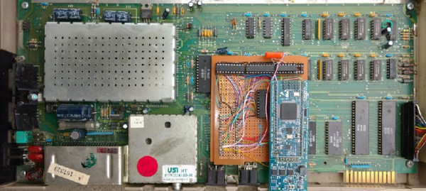
Running an emulated 6502 on an ARM chip is nothing new. What makes this build spectacular is the adaptation to the C64 motherboard. Since [telmomoya] was already breaking out the data and address lines to go to the SRAMs, it didn’t take much extra work to simply build an adapter for the DIP40 CPU socket on a C64. A few 74-series logic chips made the interface easy, and after a bit of soldering, [telmomoya] had a Commodore 64 powered by an ARM chip.

If you’re emulating one chip, you can emulate two, and with the Commodore 64, this leads to a few interesting possibilities. The C64 had a CP/M cartridge — a cartridge that contained a Z80 CPU, sharing the data and address bus with the 6510. This cartridge allowed the ‘toy computer’ C64 to run the ‘business’ CP/M operating system (and the Z80 made the Commodore 128 much cooler).  Since [telmomoya] was already emulating a CPU, emulating a second CPU wasn’t really that hard.

It’s a phenomenal build, and great if you’ve ever wanted to speed up VisiCalc.

The 2000GB IPod You Wished For In The 00’s Is An ISore

Remember those times we all said that we wouldn’t mind it if the iPod was three times as thick but could store a lot more songs and the battery lasted forever? Well, the I-Sore will let us truly consider our stance on the subject.

The iSore would have definitely made some of us the coolest kids on the yard in Jr. High (or at the engineering office) in the 00’s. At first glance we assumed it would be one of those fancy single board computers packaged with a big hard drive masquerading as an iPod. We were surprised to discover that [jimbone] was performing a classic iPod hack.

The ipod’s back is pried off and discarded. A ZIF to SATA adapter connects it to a significantly larger hard drive. The basic battery is replaced with an 8Ah pack. The USB ports are broken out. For the case there are a few options. There’s a 3D printed case, a wooden case, and even one that looks like a Lovecraftian horror.

[jimbone] claims 100 hours of playtime on a single charge. He hasn’t claimed bulking up a bit from carrying it around, but we can make our guesses.

Removing A Broken Tap From Something Really Really Expensive

What happens when you break a tap or a bolt in a component whose price tag sits in the tens of thousands. Just drilling it out and throwing in a nut insert stops being acceptable. Is there a way to remove the tap without damaging the master part at all?

Broken tap stuck in the hole it was threading

Well, that’s where [Tom Grafton] of Jerry’s Broken Drill and Tap comes in. He’s here to remove taps and chew bubblegum, and he’s definitely chewing bubble gum loudly the whole time. His primary work horse is a Metal Disintegration Machine.

A MDM is basically half of a typical wire EDM set-up. In EDM you used an electrode to punch a hole through the material. Then you thread a wire through the hole, thread it through a sometimes startling array of pulleys, and get going.

[Tom] used the MDM with an appropriately sized electrode to precisely disintegrate the middle of the tap out. After that it’s some careful work with a specially machined magnetic chisel. A quick chase of the threads with a tap and it’s back to the customer.

As you can see in the video after the break, the end result is a threaded hole that’s so indistinguishable from the rest he has to mark which one it was; presumably so the customer doesn’t forget why they’re paying him.

Continue reading “Removing A Broken Tap From Something Really Really Expensive”

Hackaday Prize Entry: DIY Foot Orthotics

What does your gait look like to your foot? During which part of your gait is the ball of your feet experiencing the most pressure? Is there something wrong with it? Can you fix it by adding or removing material from a custom insole? All these answers can be had with an expensive system and a visit to a podiatrist, but if [Charles Fried] succeeds you can build a similar system at home. 

The device works by having an array of pressure sensors on a flat insole inside of a shoe. When the patient walks, the device streams the data to a computer which logs it. The computer then produces a heat map of the person’s step. The computer also produces a very useful visualization called a gait line. This enables the orthotist to specify or make the correct orthotic.

[Charles]’s version of this has another advantage over the professional versions. His will be able to stream wirelessly to a data logger. This means you can wear the sensor around for a while and get a much more realistic picture of your gait. Like flossing right before the dentist, many people consciously think about their gait while at the foot doctor; this affects the result.

He currently has a prototype working. He’s not sure how long his pressure sensors will last in the current construction, and he’s put wireless logging on hold for now. However, the project is interesting and we can’t wait to see if [Charles] can meet all his design goals.

The HackadayPrize2016 is Sponsored by:

Blinktronicator’s POV Sends Our Eyebrows Rocketing Skyward

You think you’ve seen everything that there is to see regarding blinking LEDs and then a simple little trick proves you wrong. Our friend [Zach Fredin], aka [Zakqwy], added a pander mode to his blinky board which shows the Hackaday Jolly Wrencher in a Persistence of Vision mode. We love pandering, and obviously you just need to start the mode and wave the board back and forth. But in thinking the obvious you’d be wrong.

blinktronicator-board
Badass deadbug soldering to “fix” a mirrored shift register footprint

In the video after the break [Zach] demonstrates all the features of the blinktronicator and it’s recently finalized firmware. The tiny little board is a USB dongle featuring two buttons and an arc of sixteen LEDs in a rainbow of colors. When we say tiny, we mean it. Those LEDs are 0402 components and the board was small enough (and interesting enough) to receive an honorable mention in the Square Inch Project.

You would think that soldering all those LEDs by hand would be the trick, but [Zach] pulled off a much more difficult feat. Look closely at the image here (or click to embiggen). The two shift register footprints on the prototype were mirrored. He deadbug soldered each of them using — get this — the individual strands from some 28 AWG stranded wire. You sir, get the hardcore hand soldering badge and then some.

Okay, we’ll stop beating around the bush. The ATtiny45 on this board isn’t connected to the USB data lines, they’re only for power. That means, at its heart this is purely a blinking LED project, albeit one that uses the huge range of colors of the PICOLED family of parts. [Zach] did well with just two user inputs, but it’s the very simple POV party trick that really sucked us in. Instead of waving the board around, [Zach] uses a metal offset spatula as a mirror. Moving it back and forth unfolds the carefully timed flashes to draw your message in the air. Such a simple concept, but so satisfying to see it applied in a slightly different way.

Continue reading “Blinktronicator’s POV Sends Our Eyebrows Rocketing Skyward”

Horrible Macro Rig Makes Good Photos

We love horrible hacks like this. It’s a lens and a ring of LEDs, taped to a cell phone. Powered through crocodile clips, also taped to the cell phone. There’s nothing professional here — we can think of a million ways to tweak this recipe. But the proof of the pudding is in the tasting.

Continue reading “Horrible Macro Rig Makes Good Photos”