Gawkerbot Is Watching You

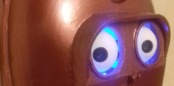
While sick with the flu a few months ago, [CroMagnon] had a vision. A face with eyes that would follow you – no matter where you walked in the room. He brought this vision to life in the form of Gawkerbot. This is no static piece of art. Gawkerbot’s eyes slowly follow you as you walk through its field of vision. Once the robot has fixed its gaze upon you, the eyes glow blue. It makes one wonder if this is an art piece, or if the rest of the robot is about to pop through the wall and attack.

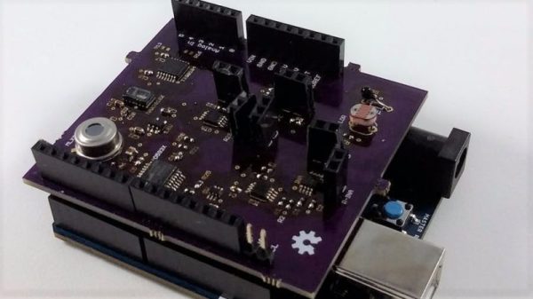
Gawkerbot’s sensing system is rather simple. A PIR sensor detects motion in the room. If any motion is detected, two ultrasonic sensors which make up the robot’s pupils start taking data. Code running on an ATmega328 determines if a person is detected on the left or right, and moves the eyes appropriately.

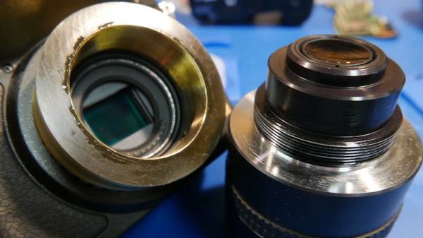
[CroMagnon] used an old CD-ROM drive optics sled to move Gawkerbot’s eyes. While the motor is small, the worm drive has plenty of power to move the 3D-printed eyes and linkages. Gawkerbot’s main face is a 3D-printed version of a firefighter’s smoke helmet.

The ultrasonic sensors work, but it took quite a bit of software to tame the jitters noisy data stream. [CroMagnon] is thinking of using PIR sensors on Gawkerbot 2.0. Ultrasonic transducers aren’t just for sensing. Given enough power, you can solder with them. Ultrasonics even work for wireless communications.

Check out the video after the break to see Gawkerbot in action.

Continue reading “Gawkerbot Is Watching You”

A Cool Mist That Dries Your Clothes

This one is both wild enough to be confused as a conspiracy theory and common sense enough to be the big solution staring us in the face which nobody realized. Until now. Oak Ridge National Laboratory and General Electric (GE), working on a grant from the US Department of Energy (DOE), have been playing around with new clothes dryer technology since 2014 and have come with something new and exciting. Clothes dryers that use ultrasonic traducers to remove moisture from garments instead of using heat.

If you’ve ever seen a cool mist humidifier you’ll know how this works. A piezo element generates ultrasonic waves that atomize water and humidify the air. This is exactly the same except the water is stored in clothing, rather than a reservoir. Once it’s atomized it can be removed with traditional air movement.

This is a totally obvious application of the simple and inexpensive technology — when the garment is laying flat on a bed of transducers. This can be implemented in a press drying system where a garment is laid flat on a bed or transducers and another bed hinges down from above. Poof, your shirt is dry in a few seconds.

But individual households don’t have these kinds of dryers. They have what are called drum dryers that spin the clothes. Reading closely, this piece of the puzzle is still to come:

They play [sic] to scale-up the technoloogy to press drying and eventually a clothes dryer drum in the next five months.

We look at this as having a similar technological hurdle as wireless electricity. There must be an inverse-square law on the effect of the ultrasonic waves to atomize water as the water moves further away from the transducers. It that’s the case, tranducers on the circumference of a drum would be inefficient at drying the clothing toward the center. This slide deck hints that that problem is being addressed. It talks about only running the transducers when the fabric is physically coupled with the elements. It’s an interesting application and we hope that it could work in conjunction with traditional drying methods to boost energy savings, even if this doesn’t pan out as a total replacement.

With a vast population, cost adds up fast. There are roughly 125 M households in the United States and the overwhelming majority of them use clothes dryers (while many other parts of the world have a higher percentage who hang-dry their clothing). The DOE estimates $9 billion a year is spent on drying clothes in the US. Reducing that number by even 1/10th of 1% will pay off more than tenfold the $880,000 research budget that went into this. Of course, you have to outfit those households with new equipment which will take at least 8-12 years through natural attrition, even if ultrasonics hit the market as soon as possible.

Continue reading “A Cool Mist That Dries Your Clothes”

Retrofitting An Amstrad CPC6128 With A Floppy Emulator

In the home computer boom of 1980s Britain, you could describe Amstrad as the third-placed home-grown player after Sinclair and Acorn. If you were a computer enthusiast kid rather than a gamer kid, you wanted Acorn’s BBC Micro, your parents bought you Sinclair’s ZX Spectrum because it was cheaper, and you thought the Amstrads were cool because they came with a better monitor than your family’s cast-off 1970s TV.

Amstrad were not a computer company headed by a technical wizard, instead they were a consumer electronics company whose founder [Alan Sugar] had a keen nose for the preferences of the consumer. Thus the Amstrad machines were different from some of their competitors: they were more polished, more appliances than experimental tools. Mass storage devices such as tape decks and floppy drives were built-in, every Amstrad came with its own dedicated monitor, and keyboards were decent quality as you’d see on a “proper” computer.

The high-end Amstrad model was the CPC6128. It came with a 3″ floppy drive, and of most interest, it could run the CP/M operating system. If your parents bought you an Amstrad CPC as a 1980s teen, it wouldn’t have been this one, so they are considerably less common than their 64k brethren with the cassette deck. One has found its way into [Drygol]’s hands though, and because the vintage 3″ floppies are unobtainable nowadays he’s fitted a floppy emulator board that stores data on an SD card.

In a sense, in that this is simply the fitting of an off-the-shelf board to a computer, it’s Not A Hack. But misses the point. This is an unusual home computer from the 8-bit era and his write-up is as much a teardown as it is  a howto. We don’t often get to see inside a 6128.

Fitting the board required the fabrication of a cable, with some very neat soldering work. The board has an LCD display, which is mounted in the floppy opening with a 3D printed bezel. The result is a very usable retro computer, without too much in the way of wanton remodeling.

This is probably the first real Amstrad 6128 we’ve shown you, but that hasn’t stopped enthusiasts making a clone with original chips, and another on an FPGA.


Ultrasonic Raspberry Pi Piano

Cheap stuff gets our creative juices flowing. Case in point? [Andy Grove] built an eight-sensor HC-SR04 breakout board, because the ultrasonic distance sensors in question are so affordable that a hacker can hardly avoid ordering them by the dozen. He originally built it for robotics, but then it’s just a few lines of code to turn it into a gesture-controllable musical instrument. Check out the video, embedded below, for an overview of the features.

His Octasonic breakout board is just an AVR in disguise — it reads from eight ultrasonic sensors and delivers a single SPI result to whatever other controller is serving as the brains. In the “piano” demo, that’s a Raspberry Pi, so he needed the usual 5 V to 3.3 V level shifting in between.

The rest is code on the Pi that enables gestures to play notes, change musical instruments, and even shut the Pi down. The Pi code is written in Rust, and up on GitHub. An Instructable has more detail on the hookups.

All in all, building a “piano” out of robot parts is surely a case of having a hammer and every problem looking like a nail, but we find some of the resulting nail-sculptures arise that way. This isn’t the first time we’ve seen an eight-sensor ultrasonic setup before, either. Is 2017 going to be the year of ultrasonic sensor projects? Continue reading “Ultrasonic Raspberry Pi Piano”

How Many Watts Are You Using?

One of the best smart home hacks is implementing an energy monitor of some kind. It’s easy enough to say that you’re trying to save energy, but without the cold hard data, it’s just talk. Plus, it’s easy and a great way to build up something DIY that the whole family can use.

[Bogdan] built up a simple whole-apartment power monitor from scratch over the weekend, and he’s been nice enough to walk us through the whole procedure, starting with picking up a split-core CT sensor and ending up with a finished project.

The brains of his project are an ESP8266 module, which means that he needed to adapt the CT sensor to put out a voltage that lies within the chip’s ADC range of 0 V to 3.3 V. If you’re undertaking an energy monitor project, it’s as easy as picking the right burden resistor value and then shifting the ground-centered voltage up by 1.6 V or so. We say it’s easy, but it’s nice to have a worked example and some scope shots. The microcontroller reads the ADC frequently, does a little math, and you’re done. Continue reading “How Many Watts Are You Using?”

Hackaday Prize Entry: A Complete Suite Of Biomedical Sensors

The human body has a lot to tell us if we only have the instruments to listen. Unfortunately, most of the diagnostic gear used by practitioners is pricey stuff that’s out of range if you just want to take a casual look under the hood. For that task, this full-featured biomedical sensor suite might come in handy.

More of an enabling platform than a complete project, [Orlando Hoilett]’s shield design incorporates a lot of the sensors we’ve seen before. The two main modalities are photoplethysmography, which uses the MAX30101 to sense changes in blood volume and oxygen saturation by differential absorption and reflection of light, and biopotential measurements using an instrumentation amplifier built around an AD8227 to provide all the “electro-whatever-grams” you could need: electrocardiogram, electromyogram, and even an electrooculogram to record eye movements. [Orlando] has even thrown on temperature and light sensors for environmental monitoring.

[Orlando] is quick to point out that this is an educational project and not a medical instrument, and that it should only ever be used completely untethered from mains — battery power and Bluetooth only, please. Want to know why? Check out the shocking truth about transformerless power supplies.

Thanks to [fustini] for the tip.

Lens Mount

X-Ray Imaging Camera Lens Persuaded To Join Micro Four Thirds Camera

Anyone who is into photography knows that the lenses are the most expensive part in the bag. The larger the aperture or f-stop of the lens, the more light is coming in which is better for dimly lit scenes. Consequently, the price of the larger glass can burn a hole in one’s pocket. [Anthony Kouttron] decided that he could use a Rodenstock TV-Heligon lens he found online and adapt it for his micro four-third’s camera.

The lens came attached to a Fischer Imaging TV camera which was supposedly part of the Fluorotron line of systems used for X-ray imaging. We find [Anthony’s] exploration of the equipment, and discovery of previous hacks by unknown owners, to be entertaining. Even before he begins machining the parts for his own purposes, this is an epic teardown he’s published.

Since the lens was originally mounted on a brass part, [Anthony Kouttron] knew that it would be rather easy to machine the custom part to fit standardized lens adapters. He describes in detail the process for cleaning out the original mount by sanding, machining and threading it. Along the way you’ll enjoy his tips on dealing with a part that, instead of being a perfect circle on the outside, had a formidable mounting tab (which he no longer needed) protruding from one side.

The video after the break shows the result of shooting with a very shallow depth of field. For those who already have a manual lens but lack the autofocus motor, a conversion hack works like a charm as well.

Continue reading “X-Ray Imaging Camera Lens Persuaded To Join Micro Four Thirds Camera”