Bomb Defusal Fun With Friends!

Being a member of the bomb squad would be pretty high up when it comes to ranking stressful occupations. It also makes for great fun with friends. Keep Talking and Nobody Explodes is a two-player video game where one player attempts to defuse a bomb based on instructions from someone on the other end of a phone. [hephaisto] found the game great fun, but thought it could really benefit from some actual hardware. They set about building a real-life bomb defusal game named BUMM.

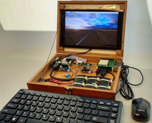
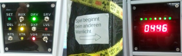
The “bomb” itself consists of a Raspberry Pi brain that communicates with a series of modules over a serial bus. The modules consist of a timer, a serial number display, and two “riddle” boxes covered in switches and LEDs. It’s the job of the bomb defuser to describe what they see on the various modules to the remote operator, who reads a manual and relays instructions based on this data back to the defuser. For example, the defuser may report seeing a yellow and green LED lit on the riddle module – the operator will then look this up and instruct the defuser on which switches to set in order to defuse that part of the bomb. It’s the challenge of quickly and accurately communicating in the face of a ticking clock that makes the game fun.

[hephaisto] took this build to Make Rhein-Main 2017, where they were very accepting of a “bomb” being brought onto the premises. The game was setup in a booth with an old analog S-video camera feed and a field telephone for communication – we love the detail touches that really add atmosphere to the gameplay experience.

Overall, it’s a great project that could easily be recreated by any hackerspace looking for something fun to share on community nights. The build files are all available on the project GitHub so it’s easy to see the nuts and bolts of how it works.

We’ve seen builds that bring video games into the real world before – like this coilgun Scorched Earth build. Fantastic.

Your VR Doesn’t Stink (Yet)

What does it smell like when the wheels heat up on that Formula 1 car you drive at night and on the weekends? You have no idea because the Virtual Reality experience that lets you do so doesn’t come with a nasal component. Yet.

Shown here is an olfactory device that works with Oculus Rift and other head-mounted displays. The proof of concept is hte work of [Kazuki Hashimoto], [Yosuke Maruno], and [Takamichi Nakamoto] and was shown of at last year’s IEEE VR conference. It lets the wearer smell the oranges when approaching a tree in a virtual environment. In other words, it makes your immersive experience smelly.

As it stands this a pretty cool little device which atomizes odor droplets while a tiny fan wafts them to the wearer’s nose. There is a paper which presumably has more detail but it’s behind a pay wall so for now check out the brief demo video below. Traditionally an issue with scent systems is the substance stuck in the lines, which this prototype overcomes with direct application from the reservoir. Yet to be solved is the availability for numerous different scents.

This build came to our attention via an UploadVR article that does a good job of covering some of the scent-based experiments over the years. They see some of the same hurdles we do: odors linger and there is a limited palette that can be produced. We assume the massive revenue of the gaming industry is going to drive research in this field, but we won’t be lining up to smell gunpowder and dead bodies (or rotting zombies) anytime soon.

The more noble effort is in VR applications like taking the elderly and immobile back for another tour of places they’ll never again be able to visit in their lives. Adding the sense of smell, which has the power to unlock so many memories, makes that use case so much more powerful. We think that’s something everyone can be hopeful about!

Continue reading “Your VR Doesn’t Stink (Yet)”

Negative Resistance: It Shouldn’t Make Sense!

When you leaf through a basic electronics textbook, you’ll find chapters describing in detail the operation of the various components. Resistors, capacitors, inductors, and semiconductors. The latter chapter will talk about P and N type regions, introduce us to the diode, and then deal with the transistor: its basic operation, how to bias it, and the like.

A tunnel diode amplifier circuit. Chetvorno [CC0]
Particularly if your textbook is a little older, you may find a short section talking about the tunnel diode. There will be an odd-looking circuit that seems to make no sense at all, an amplifier formed from just a forward-biased diode and a couple of resistors. This logic-defying circuit you are told works due to the tunnel diode being of a class of devices having a negative resistance, though in the absence of readily available devices for experimentation it can be difficult to wrap your head around.

We’re all used to conventional resistors, devices that follow Ohm’s Law. When you apply a voltage to a resistor, a current flows through it, and when the voltage is increased, so does the current. Thus if you use a positive resistance device, say a normal resistor, in both the top and the bottom halves of a potential divider, varying the voltage fed into the top of the divider results in the resistor behaving as you’d expect, and the voltage across it increases.

In a negative resistance device the opposite is the case: increasing the voltage across it results in decreasing current flowing through it. When a large enough negative resistance device is used in the lower half of a resistive divider, it reduces the overall current flowing through the divider when the input voltage increases. With less current flowing across the top resistor, more voltage is present at the output. This makes the negative resistor divider into an amplifier.

The tunnel diodes we mentioned above are probably the best known devices that exhibit negative resistance, and there was a time in the early 1960s before transistors gained extra performance that they seemed to represent the future in electronics. But they aren’t the only devices with a negative resistance curve, indeed aside from other semiconductors such as Gunn diodes you can find negative resistance in some surprising places. Electrical arcs, for example, or fluorescent lighting tubes.

A typical negative resistance I-V curve. Chetvorno [CC0]
The negative resistance property of electric arcs in particular produced a fascinating device from the early twentieth century. The first radio transmitters used an electric arc to generate their RF, but were extremely inefficient and wideband, causing interference. A refinement treated the spark not as the source of the RF but as the negative resistance element alongside a tuned circuit in an oscillator, These devices could generate single frequencies at extremely high power, and thus became popular as high-powered transmitters alongside those using high-frequency alternators until the advent of higher powered tube-based transmitters around the First World War.

It’s unlikely that you will encounter a tunnel diode or other similar electronic component outside the realm of very specialist surplus parts suppliers. We’ve featured them only rarely, and then they are usually surplus devices from the 1960s. But understanding something of how they operate in a circuit should be part of the general knowledge of anyone with an interest in electronics, and is thus worth taking a moment to look at.

1N3716 tunnel diode header image: Caliston [Public domain].

Cigar Box Opens To Raspberry Pi Laptop

If you were to go back to the middle years of the twentieth century and talk to electronic constructors, you would find a significant number had a cigar box radio among their projects. Cigar boxes were fairly robust, readily available, and could easily accommodate the parts required to make a crystal set or a simple one-tube regenerative receiver. These days there isn’t much attraction to a simple AM radio though, so while they can still be fun to build, the cigar box radio only occupies a niche in vintage radio circles.

Cigar boxes, however, remain. [Mike] found a very nice antique cigar box, and made something unexpected, he put a Raspberry Pi in it and made something close to a laptop. Into the lid goes an LCD screen secured with wooden blocks, while in the body of the box goes the LCD controller, Pi 3, and battery charger and PSU modules. There are two sets of cells, one each for screen and Pi.

We like the idea and we like his write-up for its clear run-down of the modules required even though it’s mostly a plug-together build. We described it as “Something close to a laptop” because it has one glaring omission. He’s using an external keyboard rather than having incorporated one within the case. We think there looks as though there is plenty of room for one, so perhaps he’ll return to the project and upgrade it in that way. For reminding us that cigar boxes can make excellent laptop cases though, we’re thankful.

We’ve featured numbers of Raspberry Pi laptops over the years since the little computer’s launch. Just a small selection are this one using the official touch screen, a rather beautiful one in the style of a Psion palmtop, and one that is rather chunky but has a small footprint. Meanwhile in cigar boxes, we’ve brought you an excellent little 555 organ.

Fix-a-Brick: Fighting The Nexus 5X Bootloop

Oh Nexus 5X, how could you? I found my beloved device was holding my files hostage having succumbed to the dreaded bootloop. But hey, we’re hackers, right? I’ve got this.

It was a long, quiet Friday afternoon when I noticed my Nexus 5X was asking to install yet another update. Usually I leave these things for a few days before eventually giving in, but at some point I must have accidentally clicked to accept the update. Later that day I found my phone mid-way through the update and figured I’d just wait it out. No dice — an hour later, my phone was off. Powering up led to it repeatedly falling back to the “Google” screen; the dreaded bootloop.

Stages of Grief

I kept my phone on me for the rest of the night’s jubilant activities, playing with it from time to time, but alas, nothing would make it budge. The problem was, my Nexus still had a full day’s video shoot locked away on its internal flash that I needed rather badly. I had to fix the phone, at least long enough to recover my files. This is the story of my attempt to debrick my Nexus 5X.

Continue reading “Fix-a-Brick: Fighting The Nexus 5X Bootloop”

Scratch-built Camera Gimbal For Photographer With Cerebral Palsy

We so often hack for hacking’s sake, undertaking projects as a solitary pursuit simply for the challenge. So it’s nice to see hacking skills going to good use and helping someone out. Such was the case with this low-cost two-axis handheld camera gimbal intended to help a budding photographer with a motion disorder.

When [Tadej Strah] joined his school photography club, a fellow member who happens to have cerebral palsy needed help steadying cameras for clean shots. So rather than shell out a lot of money for a commercial gimbal, [Tadej] decided to build one for his friend. A few scraps of aluminum bar stock were bent into the gimbal frames and camera mount. Two hobby servos take care of the pitch and roll axes, controlled by an Arduino talking to an MPU-6050. Mounted to a handle from an angle grinder with the battery and electronics mounted below, the gimbal looks well-balanced and does a good job of keeping the camera level.

Hats off to [Tadej] for pitching in and solving a real world problem with his skills. We like to see people helping others directly, whether it’s building a gyroscopic spoon for Parkinson’s sufferers or vision enhancement for a nearly blind adventurer.

Continue reading “Scratch-built Camera Gimbal For Photographer With Cerebral Palsy”

Ask Hackaday: Frequency Hopping On The NRF24l01+?

We’ve seen a lot of hacks with the nRF24l01+ 2.4 GHz radio modules. The tiny chips pack a lot of bang for the buck. Since the radios can switch frequencies relatively quickly, [Shubham Paul] decided to take advantage of this feature to make a rudimentary frequency-hopping communications channel.

The code is actually incredibly simple. Both the transmitter and receiver simply scan up and down over the defined channels. Because the clock speeds of any given pair of Arduinos are likely to be slightly different, it’s not a surprise that the radios eventually drift out of sync. Right now, as a quickie solution, [Shubham] is using a serial-port resynchronization: both are connected to the same computer, and he just tells them to get on the same channel. That’s not a horribly satisfying workaround. (But it’s a great start!)

Keeping two radios that are continually swapping channels in sync is no easy task, but it could possibly be made easier by taking advantage of the nRF’s acknowledge mode. If the delay between a sent acknowledge message and a received one were constant, these events (one on TX and one on RX) could be used to re-sync the two hopping cycles. All of this would probably require more temporal resolution than you’re going to get out of a microprocessor running Arduino code, but should be possible using hardware timers. But this is pure speculation. We briefly looked around and couldn’t find any working demos.

So Hackaday, how would you remotely sync two nRF24s on the cheap? Or is this a crazy idea? It might help to make transmissions more reliable in the face of 2.4 GHz band interference. Has anyone implemented their own frequency hopping scheme for the nRF24l01+?