An Incredible ATX Amiga 4000 Motherboard

No matter how far modern computer hardware advances, there’s still a fairly large group of people who yearn for the early days of desktop computing. There’s something undeniably appealing about these early systems, and while even the most hardcore vintage computer aficionado probably wouldn’t be using one as their daily computer anymore, it’s nice to be able to revisit them occasionally. Of course the downside of working with computers that may well be older than their operators is that they are often fragile, and replacement parts are not necessarily easy to come by.

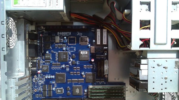
But thanks to projects like this impressive ATX Amiga 4000 motherboard shown off by [hese] on the Amibay forums, getting first hand experience with classic computing doesn’t necessarily mean relying on vintage hardware. By making an Amiga that’s compatible with standard ATX computer cases and power supplies, it becomes a bit more practical to relive the Commodore glory days. Right now it’s mainly a personal project, but if there’s sufficient interest it sounds as if that might change.

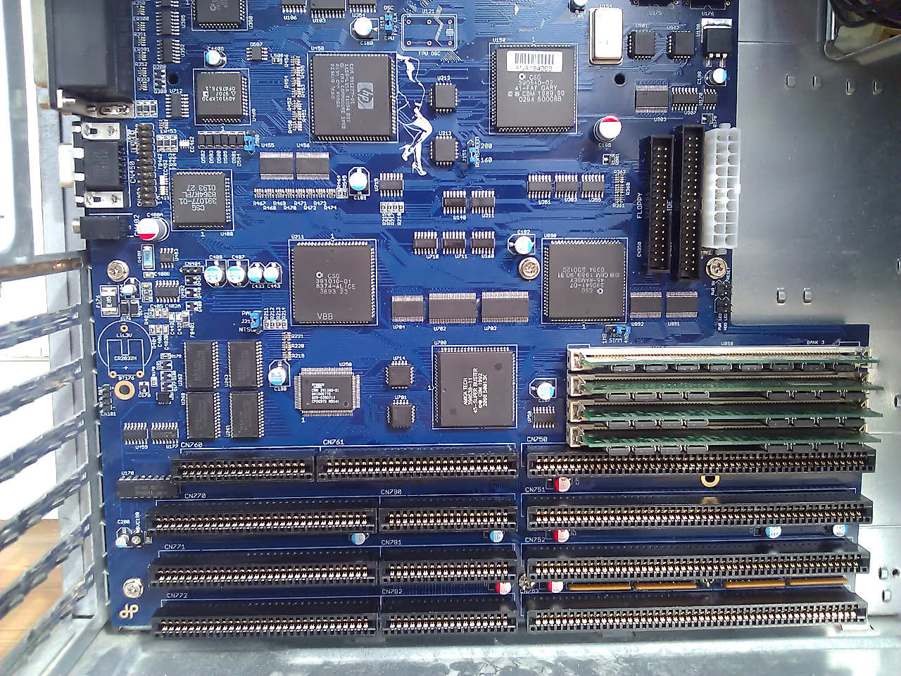
This board could be considered a modern reincarnation of the Amiga 4000T, which was an official tower version of the standard Amiga 4000 released by Commodore in 1994. It features a 68030 CPU, with 16 MB Fast RAM and 2 MB Chip RAM. For expansion there are four full-length Zorro III slots and three ISA slots, as well as IDE ports for a floppy and hard drive.

The board really looks the part of a professionally manufactured computer motherboard from the late 1990s, which speaks not only to the attention to detail [hese] put into its design, but the manufacturing capabilities that are now available to the individual. With passionate people like this involved, it’s hardly surprising that the vintage computer scene is so vibrant.

Of course, this isn’t the first newly built “vintage” computer we’ve seen here at Hackaday. From bare-minimum 8085 computers to the comparative luxury of the 6502-powered Cactus, it seems like what’s old is new again.

[Thanks to Laurens for the tip.]

Build Your Own Two-Stage Water Rockets

Water rockets are one of the most fun and exciting science-adjacent activities one can take part in during the summer, and are popular with children and adults alike. Designs range from a bike pump with a cork in a bottle, up to significantly more advanced hardware. [Air.command]’s two-stage water rocket definitely fits into the latter category.

The build is initially somewhat confronting in its complexity, but after a thorough read-through the operating principles become clear. It’s an all-mechanical setup which relies on the weight of the upper stage and the initial acceleration of the rocket to keep the two stages coupled. It’s only when the first stage stops delivering thrust that a spring forces the two stages apart, and the upper stage rockets ever higher.

Parts-wise, everything is fairly accessible – with pieces cribbed from garden hose fittings, retractable pens and other household ephemera. It’s not the easiest thing to put together, but with perseverance and some tweaking and tuning, it’s definitely achievable for the home gamer, with no advanced tools or techniques required.

Now that you’ve got a two-stage rocket under construction, you might want to consider upgrading your launchpad. Video after the break.

Continue reading “Build Your Own Two-Stage Water Rockets”

Better Ways To Drive Nixie Tubes

Ah, Nixie tubes. You’re not cool unless you have a few Nixie tubes sitting around, and you’re not awesome unless you’ve built your own Nixie tube clock. That’s what [Thomas] is doing for his entry into the Hackaday Prize, and he’s come up with a very low-cost way of doing it.

For the high voltage supply of this build, [Thomas] is turning to one of the standard circuits based on the MC34063 that’s simple enough and good enough to make everything work. There are really no surprises with the power supply here. This is all a project about turning on different digits inside the Nixie, though, and for that [Thomas] spun his own board capable of driving a pair of IN-1 Nixies with a single ATMega8.

These two-Nixie boards are daisy chained together through a UART connection, where each board passes digits down the line. For example, the first board receives, 12, 30, and 59, displays 59, and passes 12 and 30 down to the next boards. The second board then displays 30 and passes 12 to the last board.

Of course, if you’ve designed a Nixie driver, the next thing to do is to build a clock. [Thomas] had the rather clever idea of making an enclosure for this clock out of concrete, using a 3D printed interior mold. Everything seemed to be going well until it was time to pull the interior mold out, and a few light taps resulted in some fairly large cracks. That’s disappointing, but with a slight redesign and some more fibers in the concrete mix, this is going to turn out to be a weighty win.

Simulate PIC And Arduino/AVR Designs With No Cloud

I’ve always appreciated simulation tools. Sure, there’s no substitute for actually building a circuit but it sure is handy if you can fix a lot of easy problems before you start soldering and making PCBs. I’ve done quite a few posts on LTSpice and I’m also a big fan of the Falstad simulator in the browser. However, both of those don’t do a lot for you if a microcontroller is a major part of your design. I recently found an open source project called Simulide that has a few issues but does a credible job of mixed simulation. It allows you to simulate analog circuits, LCDs, stepper and servo motors and can include programmable PIC or AVR (including Arduino) processors in your simulation.

The software is available for Windows or Linux and the AVR/Arduino emulation is built in. For the PIC on Linux, you need an external software simulator that you can easily install. This is provided with the Windows version. You can see one of several videos available about an older release of the tool below. There is also a window that can compile your Arduino code and even debug it, although that almost always crashed for me after a few minutes of working. As you can see in the image above, though, it is capable of running some pretty serious Arduino code as long as you aren’t debugging.

Continue reading “Simulate PIC And Arduino/AVR Designs With No Cloud”

Friday Hack Chat: Hacking For Mental Health

Quite often we see applications of hacking and DIY in the medical field. From 3D printed prosthetics to hacked insulin pumps, there’s a wide variety of stuff you can do, but what about psychology? That’s what our Hack Chat this Friday is all about.

Our guest for this week’s Hack Chat is Curt White. He’s been building medical devices for years, and when he’s not doing that he’s creating interactive installation art and costumes. At work he’s a device and sensor developer at the Child mind Institute MATTER Lab where he designs and researches wearable medical devices for children with mental health issues. He’s currently working on gesture detection using wearables, machine learning optimized for microcontrollers, and building and fixing prototypes.

For this hack chat, we’ll talk about how mental health can be addressed by building things with a focus on wearable devices and sensor data. How are wearables challenging the outdated and arbitrary classification of psychiatric disorders, and what is the potential for audio, EEG, and fMRI to help us progress beyond checklist diagnosis? We’ll also talk about:

  • Hacking for mental health
  • Addressing the intangible with the tangible
  • Working with medical researchers
  • The fact that you don’t need an IRB if you don’t accept federal funding, or are working in Belize.

You are, of course, encouraged to add your own questions to the discussion. You can do that by leaving a comment on the Hacking For Mental Health Event Page and we’ll put that in the queue for the Hack Chat discussion.join-hack-chat

Our Hack Chats are live community events on the Hackaday.io Hack Chat group messaging. This week is just like any other, and we’ll be gathering ’round our video terminals at noon, Pacific, on Friday, August 24th. Need a countdown timer? Go go go

Click that speech bubble to the right, and you’ll be taken directly to the Hack Chat group on Hackaday.io.

You don’t have to wait until Friday; join whenever you want and you can see what the community is talking about.

Measure Resistance The Colourful Way

One of the first things anyone with an interest in electronics learns is the resistor colour code. The colour of the first band reveals the first figure, the second the subsequent figure, and the third a power-of-ten multiplier. At first you learn these colours, but eventually you just recognise the values through familiarity. You don’t have to think about multipliers when you see orange-orange-red, you just know that it’s a 3K3 resistor.

[Plusea] has come up with an entertaining interface for an ohmmeter, which instead of displaying the resistance on an LCD or a meter shows it as the colours of the code, via a set of addressable LEDs. The work is done by an ATtiny85 microcontroller, and the whole thing is mounted on a flexible PCB (fabrication of which is itself interesting, placing cut copper traces on a sheet of kapton and covering with a second kapton layer cut to be the solder mask). There is even a clever integration of a CR2032 battery holder from the PCB itself, though they admit that it could be made more compact with the use of SMD components instead of through-hole.

The write-up and associated photo album tells us a lot about the project, but is missing a crucial detail: a shot of it working. We’ll give them the benefit of the doubt on that front though, because we like the idea and its execution.

Strangely, this isn’t the first ohmmeter to use the resistor colour code in this way, we’ve previously brought you one featuring a light-up giant resistor.

Ask Hackaday Answered: The Tale Of The Top-Octave Generator

We got a question from [DC Darsen], who apparently has a broken electronic organ from the mid-70s that needs a new top-octave generator. A top-octave generator is essentially an IC with twelve or thirteen logic counters or dividers on-board that produces an octave’s worth of notes for the cheesy organ in question, and then a string of divide-by-two logic counters divide these down to cover the rest of the keyboard. With the sound board making every pitch all the time, the keyboard is just a simple set of switches that let the sound through or not. Easy-peasy, as long as you have a working TOG.

I bravely, and/or naïvely, said that I could whip one up on an AVR-based Arduino, tried, and failed. The timing requirements were just too tight for the obvious approach, so I turned it over to the Hackaday community because I had this nagging feeling that surely someone could rise to the challenge.

The community delivered! Or, particularly, [Ag Primatic]. With a clever approach to the problem, some assembly language programming, and an optional Arduino crystalectomy, [AP]’s solution is rock-solid and glitch-free, and you could build one right now if you wanted to. We expect a proliferation of cheesy synth sounds will result. This is some tight code. Hat tip!

Squeezing Cycles Out of a Microcontroller

Let’s take a look at [AP]’s code. The approach that [AP] used is tremendously useful whenever you have a microcontroller that has to do many things at once, on a rigid schedule, and there’s not enough CPU time between the smallest time increments to do much. Maybe you’d like to control twelve servo motors with no glitching? Or drive many LEDs with binary code modulation instead of primitive pulse-width modulation? Then you’re going to want to read on.

There are two additional tricks that [AP] uses: one to fake cycles with a non-integer number of counts, and one to make the AVR’s ISR timing absolutely jitter-free. Finally, [Ag] ended up writing everything in AVR assembly language to make the timing work out, but was nice enough to also include a C listing. So if you’d like to get your feet wet with assembly, this is a good start.

In short, if you’re doing anything with hard timing requirements on limited microcontroller resources, especially an AVR, read on!

Continue reading “Ask Hackaday Answered: The Tale Of The Top-Octave Generator”