Detecting Cars With An ESP8266 Magnetometer

Having a motorized gate on your driveway is great, but only if there’s an easy way to trigger it. [Andrew] says the gate at his parent’s place could only be controlled by manually pushing a button on the panel or with a dinky remote that didn’t have nearly the range they wanted. So he decided to build his own magnetometer allowing the gate to automatically open when a car was trying to leave.

Naturally, there are commercial offerings that would solve this problem. But with a sticker price of more than $150 USD, [Andrew] was more than happy to spend a bit of time tinkering to get the job done for less than 1/10th the cost with an ESP8266 and a QMC5883X series magneto-resistive sensor. Of course, this is one of those projects that seems simple enough in your head, but ends up taking a bit of finesse to pull off in the real-world.

For one, [Andrew] had to figure out how to prevent false positives. Pretty much any object brought close enough to the sensor, including his hand, would cause it to react. He ended up coming up with a way to use a rolling average to prevent the gate from firing off just because a squirrel ran past. The built-in safeties are designed to ensure that the gate only opens when an actual car is sitting in the appropriate spot for long enough.

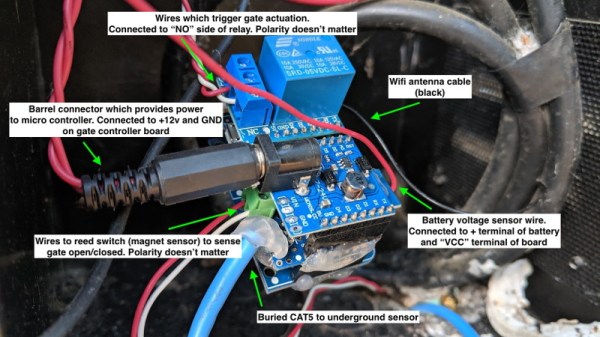
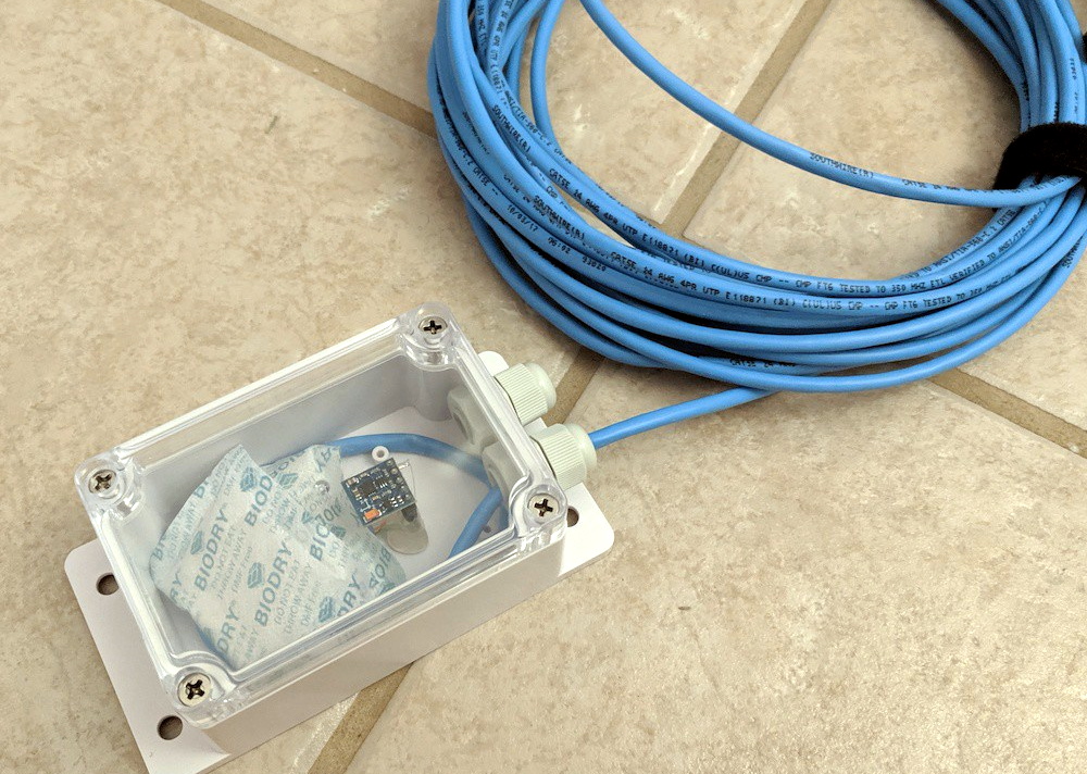
Speaking of, we love how [Andrew] deployed the QMC5883X sensor for this project. The small sensor board and a few moisture-absorbing packets were placed in a Sonoff IP66 waterproof enclosure, and buried under the rocks of the driveway. A standard CAT5 cable is used to tether it to the ESP8266, relay, and assorted other goodies that now live in the gate’s control box. In the future he says the cable will likely have to go into a conduit, but for now the system is working more or less how he expected.

If your estate isn’t quite palatial enough to have a motorized gate out front, we’ve seen plenty of projects that add some much-needed intelligence to the humble garage door opener which might be more your speed.

Core Rope Memory Makes One Of The Oddest LED Flashers We’ve Ever Seen

If you’ve heard of core rope memory, it will probably be in the context of vintage computing equipment such as Apollo-era NASA hardware. A string of magnetic cores and sense wires form a simple ROM arrangement, which though long-ago-superceded by semiconductor memory remains possible to recreate by the experimenter. It’s a path [Nicola Cimmino] has trodden, as he’s not only made a few nibbles of core rope memory, but incorporated it with an Arduino as part of one of the most unusual LED flashers we’ve ever seen. The memory holds a known sequence of bits which is retrieved in sequence by the Arduino, and the LED is kept flashing as long as the read values conform to those expected.

The memory itself is simple enough (and not to be confused with magnetic core memory). The cores are ferrite rings that form a sequence of small transformers that become the bits of the memory. Individual bits are set high or low by either passing a sense wire through a core to create a primary, or bypassing it. Multiple sense wires can be used for separate nibbles in the same cores, so for example his four nibbles all share the same four cores. Pulses are sent down the wires, either passing through a core or not, and equivalently picked up or not on sense lines.

In this case the sense wire is driven directly to ground by Arduino pins which means that the circuit is relying upon the current limiting of the ATmega328 to avoid destroying itself, it’s possible we’d add a driver transistor. The bits are read meanwhile from the secondary windings through a diode rectifier and capacitor to an Arduino analogue pin.

Core memory has been paired with an Arduino before on these pages, though of the RAM variety.

This CT Scan Of A PCB Is The Accidental ASMR We Didn’t Know We Needed

At risk of getting any ASMR buffs who might be reading cranky because there’s no audio, [Chris], or [@no1089] on Twitter, has gifted us with this visually stunning scan of his Maxim MAX86160 in-ear heart monitor mounted on a rigidflex PCB. You can take a look, in the video below the break.

If you’re wondering why anyone would scan a board, other than boredom, know that it’s actually quite common. X-Ray machines are commonly used as a quick, passive way to check a board that’s fresh off the production line. These aren’t the X-Rays like those of broken bones you’re (hopefully not too) used to seeing though, they’re Computed Tomography scans (CT scans, CAT scans), in effect just 3D X-Rays.

CT Scan of a BGA

For electronics manufacturers and assemblers, CT scans are incredibly useful because they provide a non-destructive way to check for errors. For example, how do you know if that middle BGA pin is actually soldered correctly? You could run a functional test and make sure everything is working (at least, everything you check), but that takes time. The longer it takes to validate, the higher the manufacturing cost. In manager speak: “cost bad. Fast good.”

It’s also common to use a CT scan to create a full 3D model of a board. This makes it easy to check every little detail, especially the ones that are visually obscured by surface mount devices or critical signal paths that are buried under board layers.

Highlight of solder joints on small-outline integrated circuit (SOIC) to a PCB’s pads.

If you want to geek out on CT scans, you can learn more about the lab that did this scan or by wading into this unclassified research paper from Australia’s Cyber and Electronic Warfare Division.

But we know you really want more of this video, but better. And we’ve got the goods. For the chill folk among you, here’s a 55-minute version without all the CT scan info cluttering the screen. For those of you currently blasting eDM in your headphones, here’s a 30 second clip of it looping at ~5x speed. Eat your heart out:

Continue reading “This CT Scan Of A PCB Is The Accidental ASMR We Didn’t Know We Needed”

BST-863 Hot Air Rework Station Teardown

[Voltlog] has had a 952 hot air rework station for a long time. You’ll recognize it when you see it — they are the ubiquitous soldering iron and hot air gun combination from China sold under numerous brand names. He didn’t think the old station was as good as some of the newer devices available, and did a teardown and review of the BST-863 station that can be had for well under $200. You can see the video below.

He was impressed with the build quality of the workpiece holder. It lets you store the hot air gun and keep it in standby mode. He liked the touchscreen, too, although the beeping seemed a bit annoying. However, in general, the operating noise was less than the older unit it replaced.

Continue reading “BST-863 Hot Air Rework Station Teardown”

Everything You Wanted To Know About Padauk MCUs And More

At this point you’d need to have lived underneath a rock somewhere on the dark side of the Moon to not have heard about these amazing, 3-cent microcontrollers. A number of places have pitched in on them, but comprehensive reviews, let alone a full-blown review of the entire ecosystem surrounding these Padauk MCUs have been scarce. Fortunately, [Jay Carlson] has put in a lot of effort to collect everything you could possibly want to know about anything Padauk.

The most important take-away is that these MCUs do not have any kind of communication peripherals. UARTs, I2C, and SPI all have to be done in software. They’re not very great at low-power or battery-powered applications due to high power usage. Essentially you’ll be using GPIO pins a lot. On the other hand, its multi-CPU context, FPPA feature is rather interesting, with the article covering it in detail.

As for the development tools, [Jay] came away very impressed with the In-Circuit Emulation (ICE) instead of running code on an MCU, as this can reduce development times significantly. This makes even the OTP (one-time programmable) property of most Padauk MCUs less significant than one might at first assume.

Then there’s the actual programming of the MCUs. The Micro C compiler Padauk provides essentially implements a sub-set of the C language, with some macros to replace things like for loops. Initially this may seem like a weird limitation, until you realize that these MCUs have 64 to 256 bytes of SRAM. That’s bytes, without any prefixes.

Finally, [Jay] shows off a couple of test projects, including a NeoPixel SPI adapter and bike light, which are all available on Github. The WS2812b project is something we have seen before, for example this project from [Anders Nielsen] (featured in the article image), which provides another take on this range of MCUs.

Did reading [Jay]’s article change your mind on these Padauk parts? Have you used these MCUs and ICE parts before? Feel free to leave your thoughts in the comments.

Solder Ninja Dabbles In USB Power Arcana

USB first hit the scene in the 1990s, and was intended to simplify connecting peripherals to PCs and eliminate the proliferation of various legacy interfaces. Over 20 years later, it’s not only achieved its initial goals, but become a de facto standard for charging and power supply for all manner of personal electronic gadgets. If you asked someone back in 1995 whether or not you could build a USB-powered soldering iron, they’d have politely asked you to leave the USB Implementers Forum. But times change, and Solder Ninja is just that!

With a maximum power draw of 40 W, the Solder Ninja required careful design to ensure practicality. It supports a variety of USB power standards, including USB-BC 1.2, USB Quick Charge, and USB Power Delivery. This enables it to draw the large amounts of current required for the heating element. To make it easy to use with a variety of chargers out in the wild, it displays the current negotiated voltage and maximum current draw. This enables the user to understand the varying performance of the device, depending on the charger it’s plugged into.

Given the multitude of different USB power standards, we imagine [Nicolas] has the patience of a saint to perfect a project like this. We’ve seen similar builds before, too. Video after the break.

Continue reading “Solder Ninja Dabbles In USB Power Arcana”

Lego House: Right Next To Denmark’s Legoland, But Way Cooler

If there is one thing that most Hackaday readers will know about Denmark, it is that it’s the home of the Lego brick. The toy first appeared at the end of the 1940s from the factory of Ole Kirk Christiansen‘s Lego company in Billund, central Denmark, and has remained inseparable from both the town and the country ever since.

When spending a week in Denmark for the BornHack hacker camp it made absolute sense to take a day out to drive up to Billund and visit the famous Legoland theme park. All those childhood dreams of seeing the fabled attraction would be satisfied, making the visit a day to remember.

Your first view of the Lego House, in the centre of Billund.

The Danes at Bornhack however had other ideas. By all means go to Legoland they said, but also take in Lego House. As a Brit I’d never heard of it, so was quickly educated. It seems that while Legoland is a kid’s theme park, Lego House is a far more Lego-brick-focused experience, and in the view of the Danish hackers, much better.

Continue reading “Lego House: Right Next To Denmark’s Legoland, But Way Cooler”