3d printed escalator, from side, showing mechanism

Tiny 3D Printed HO Scale Escalator That Works

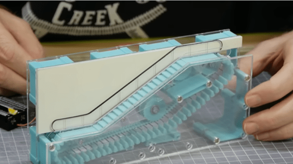
[Luke Towan] has a cool HO scale Escalator mostly made of 3D printed parts, with some laser cut acrylic, for a station on his HO model railroad.

Escalators are mesmerizing to watch – there’s something magical about the stairs unfolding at the bottom and folding up at the top. But they’re very hard to model.

[Luke Towan] has done it – his 3D printed version closely resembles the real thing mechanically. Pins are carried around, cantilevered out from a 3D printed chain. A stair swivels on each pin – at the bottom each stair’s free end rests on a ‘bottom’ far enough down for the stairs to be level, while on the incline the ‘bottom’ is just below the pins. It’s a tricky build.

If you like pushing the envelope of what 3D printing can do this is an interesting project, even if you’re not planning to build an escalator. There are lots of tips for making small mechanisms with 3D printing, and for making small mechanisms that work reliably without stuttering.

He’s not the first to build an escalator. Back in 2015 we covered this wooden escalator for slinkies,  and just recently this 3D printed version from [AlexY].


Prototyping The Prototype

For basic prototyping, the go-to tool to piece together a functioning circuit is the breadboard. It’s a great way to prove a concept works before spending money and time on a PCB. For more complex tasks we can make use of simulation software such as SPICE. But there hasn’t really been a tool to blend these two concepts together. That’s what CRUMB is hoping to solve as a tool that allows simulating breadboard circuits.

Currently, most basic circuit functions are working for version 1.0. This includes passive components like resistors, capacitors, switches, some LEDs, and potentiometers, as well as some active components like transistors and diodes. There are some logic chips available such as 74XX series chips and 555 timers, which opens up a vast array of circuit building. There’s even an oscilloscope feature, plus audio output to incorporate buzzers into the circuit simulation. Currently in development is an LCD display module and improvements to the oscilloscope.

Besides prototyping, this could be useful for anyone, students included, who is learning about circuits without the need to purchase any hardware. The major downside to this project is that it there doesn’t seem to have a free or trial version, the source is not available, and it’s only for sale on Steam, Apple Store, and Google Play. That being said, there is a forum available for users to discuss problems and needs for future versions, so it’s possible that a community could build up around it. We’ve seen previously non-free versions of circuit simulation software become more open after some time, so it’s not out of the realm of possibility.

Thanks to [Thomas] for the tip!

Interfacing An Old Engine Cowl Flaps Indicator To USB

[Glen Akins] had a WW2-era aircraft engine cowl flap indicator lying around (as you do) and thought it would make a jolly fine USB-attached indicator. The model in question is a General Electric model 8DJ4PBV DC Selsyn, which was intended for four-engined aircraft. For those not familiar with the purpose [Glen] explains in his detailed writeup, that piston-engine aircraft of that era were air-cooled, and during conditions of maximum engine power — such as during take-off — flaps on the side of the engine cowling could be opened to admit additional cooling airflow. These indicator dials were connected to a sender unit on each of the flap actuators, providing the pilots an indication of the flaps’ positions. Continue reading “Interfacing An Old Engine Cowl Flaps Indicator To USB”

This Electric Outboard Conversion Makes For A Quiet Day On The Water

Nothing beats a day on the lake in a little boat with an outboard motor putt-putting along behind you. It’s great fun, if perhaps a little noisy with all that putting going on. And maybe that oily sheen on the water in your wake is not so nice. it could be that the fish are a little annoyed with your putting, too. Come to think of it, outboard motors are a bit of a problem.

Fortunately there’s a better way, like converting an old outboard motor to electric. It comes to us by way of [Anton], who happened upon the perfect donor platform — a 5-hp outboard by Crescent, sporting a glorious 1970s color scheme and a motor housing shell perfect for modding. He started by ripping the old engine and drivetrain out of the housing to make room for the BLDC motor and its driver. The motor was a project in itself; [Anton] rewound the original stator with much thicker wire and changed the coil configuration to milk as much torque as possible out of it. What started as a 180-kv motor ended up at 77 kv with much more copper and new Hall sensors for the controller. He also put a ton of effort into waterproofing the motor with epoxy resin. With a 3D-printed prop and a streamlined fairing, the new motor looks quite at home on the outboard. In fact, the whole thing barely looks customized at all — the speed control is even right on the tiller where you’d expect it.

The video below shows the build and a test run, plus an analysis of the problems encountered, chief of which is water intrusion. But as [Anton] rightly points out, that’s easily solved by reusing the original driveshaft and mounting the motor above the waterline, like this. Still, we like the look of this, and the idea of knocking around on the water nearly silently seems wonderful.

Continue reading “This Electric Outboard Conversion Makes For A Quiet Day On The Water”

Aesthetic PCB Design Tips For Improved Functionality

Those of us hardware types that spend a lot of time designing PCBs will often look at other peoples’ designs with interest, and in some cases, considerable admiration. Some of their boards just look so good. But are aesthetics important? After all, for most products, the delicate electronic components on that PCB are tucked safely inside a protective enclosure. But, as [Phil’s Lab] explains, aesthetic PCB designs can lead to functional improvements, such that better-looking designs are also better performing, in terms of manufacturability (and therefore yield), electromagnetic compatibility (EMC), and several other factors that can be important.

First off, making a PCB easy to read and using sane placement of components and connections will speed up debugging by reducing errors. Keeping a consistent and not too-tight placement grid can give the pick and place machine an easier task, and reduce solder issues during reflow. But there are also more serious concerns, such as the enforcement of design partitionings — such as keeping analog circuits together and away from noisy power and digital areas — which can make the difference between functioning within specification, and failure.

The video goes into a few other interesting tips, one highlight is using a ground-tied PCB perimeter zone, with wavelength-of-interest via stitching. This will reduce EMC side emissions from the power plane, but also if you select an appropriate surface finish, and keep the solder mask open, you’ve got a free, full perimeter contact to ground your scope probe. Oh, and it looks good too.

Hackaday is no stranger to beautiful artistic PCBs, like the work of [Saar Drimer] and many others. But if one PCB doesn’t cut it for your needs, there’s always the ‘Oreo’ construction to consider.

Continue reading “Aesthetic PCB Design Tips For Improved Functionality”

Weird Energy Storage Solutions Could Help The Grid Go Renewable

We’re all familiar with batteries. Whether we’re talking about disposable AAs in the TV remote, or giant facilities full of rechargeable cells to store power for the grid, they’re a part of our daily lives and well understood.

However, new technologies for storing energy are on the horizon for grid storage purposes, and they’re very different from the regular batteries we’re used to. These technologies are key to making the most out of renewable energy sources like solar and wind power that aren’t available all the time. Let’s take a look at some of these ideas, and how they radically change what we think of as a “battery.”

Continue reading “Weird Energy Storage Solutions Could Help The Grid Go Renewable”

Standing Desk With A Clever Flair

Standing desks (also known as sit-stand desks) are somewhat polarizing. The height is adjustable, but the idea is that you move between sitting and standing while you work. Hundreds of manufacturers are out there, but they’re all the same. Two metal legs that extend and one or more motors to move the legs up and down. [JAR Made] tried to make something slightly different for their standing desk with an extending curved surface.

The build started with some gorgeous alder that was milled into square with a track saw and a planer — no jointer was required. However, he wanted long boards and was debating how to butt join the pieces together and decided on pocket holes with dowels to try and clamp the boards together while the glue dried. The resulting product was one that [JAR Made] was unhappy with. He pivoted on his feet by switching Baltic birch plywood for the main desk surface. Which was bent using a kerf-cutting technique (though just using a track saw rather than a CNC bit).

Here is where you can see him learn from his earlier mistakes. He routed a half lap in the plywood for the butt joint to give it more strength and devised a clever clamping mechanism using CA glue and painter’s tape to get good clamping pressure. The alder from earlier came in use to serve as a front edge for the plywood and a groove to hold the sliding piece of plywood that extends and retracts as the desk goes up and down.

Regular old standing desk legs screw into the underside of the desk and allow it to move up and down. Overall, it’s a wonderful build of a gorgeous desk. We love seeing people make mistakes and then pivot and learn from them. Perhaps the next step is to automate the desk to move on its own.

Continue reading “Standing Desk With A Clever Flair”