[James] wanted to build a BEAM turbot. He ran into some problems with the BEAM circuitry though, and ended up with a BEAM/Picaxe hybrid.
Beam robotics are the brainchild of Mark Tilden. The acronym stands for Biology, Electronics, Aesthetics, and Mechanics. BEAM based bots were very popular with hobbyists in the 90’s and early 2000’s, but popularity has since died down. BEAM robots tend not to use microcontrollers, instead attempting to simplify things down to the lowest number of elements.
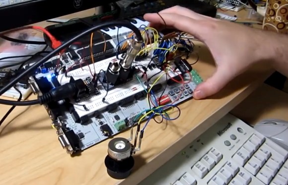
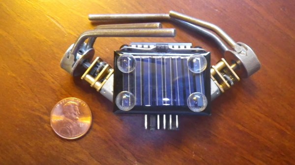
[James’] turbot uses a miller solar engine. The original design used the engine to drive a Solar Turbot Latch. [James’] problem was that the photodiode “eyes” of the robot were not properly enabling the 74AC245 to pass current to the motor. Since the robot was built in a tiny space, debugging the circuit was extremely hard. After struggling with the ‘245 for some time, [James] decided to swich out the BEAM circuit for a Picaxe microcontroller.
The Picaxe can only sink or source about 20ma per pin, which is slightly less than the no load current of [James’] motors. To make up for this, he ganged up four pins per motor. There was some risk in the motors blowing up the Picaxe. However between the lightly loaded gearmotors and low current solar panels it seems to be working just fine. Overall the bot is a very clean, compact build. Jump past the break to check out its really smooth crablike walking action.